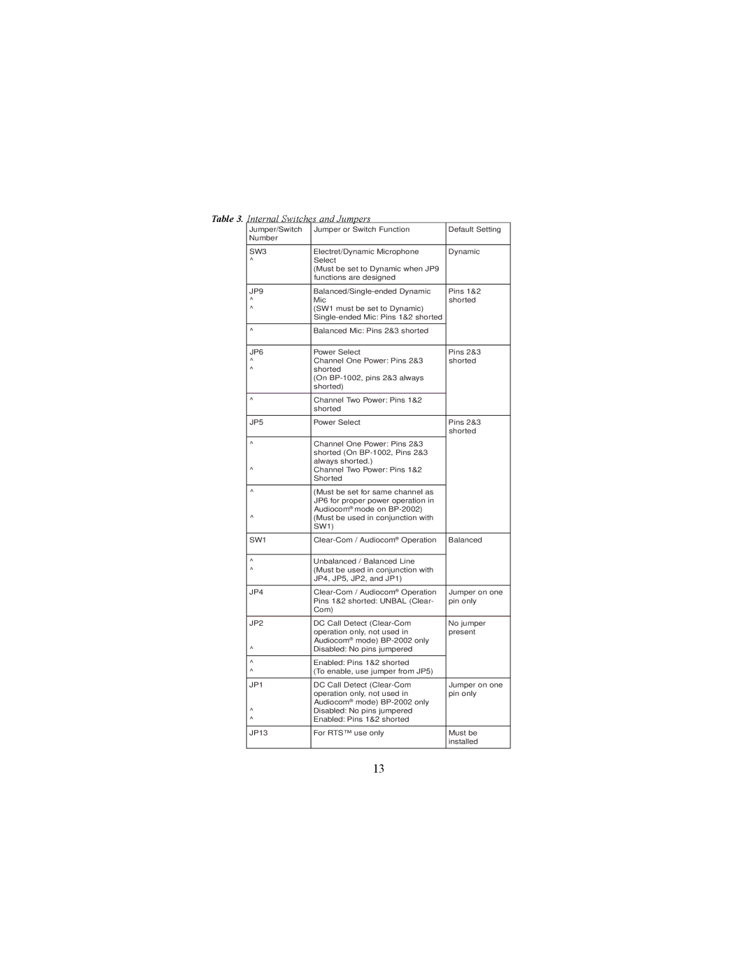
Table 3. Internal Switches and Jumpers
Jumper/Switch | Jumper or Switch Function | Default Setting |
Number |
|
|
|
|
|
SW3 | Electret/Dynamic Microphone | Dynamic |
^ | Select |
|
| (Must be set to Dynamic when JP9 |
|
| functions are designed |
|
|
|
|
JP9 | Pins 1&2 | |
^ | Mic | shorted |
^ | (SW1 must be set to Dynamic) |
|
|
| |
|
|
|
^ | Balanced Mic: Pins 2&3 shorted |
|
|
|
|
JP6 | Power Select | Pins 2&3 |
^ | Channel One Power: Pins 2&3 | shorted |
^ | shorted |
|
| (On |
|
| shorted) |
|
|
|
|
^ | Channel Two Power: Pins 1&2 |
|
| shorted |
|
|
|
|
JP5 | Power Select | Pins 2&3 |
|
| shorted |
^ | Channel One Power: Pins 2&3 |
|
| shorted (On |
|
| always shorted.) |
|
^ | Channel Two Power: Pins 1&2 |
|
| Shorted |
|
|
|
|
^ | (Must be set for same channel as |
|
| JP6 for proper power operation in |
|
| Audiocom® mode on |
|
^ | (Must be used in conjunction with |
|
| SW1) |
|
|
|
|
SW1 | Balanced | |
|
|
|
^ | Unbalanced / Balanced Line |
|
^ | (Must be used in conjunction with |
|
| JP4, JP5, JP2, and JP1) |
|
|
|
|
JP4 | Jumper on one | |
| Pins 1&2 shorted: UNBAL (Clear- | pin only |
| Com) |
|
|
|
|
JP2 | DC Call Detect | No jumper |
| operation only, not used in | present |
| Audiocom® mode) |
|
^ | Disabled: No pins jumpered |
|
|
|
|
^ | Enabled: Pins 1&2 shorted |
|
^ | (To enable, use jumper from JP5) |
|
|
|
|
JP1 | DC Call Detect | Jumper on one |
| operation only, not used in | pin only |
| Audiocom® mode) |
|
^ | Disabled: No pins jumpered |
|
^ | Enabled: Pins 1&2 shorted |
|
|
|
|
JP13 | For RTS™ use only | Must be |
|
| installed |
|
|
|
13
