Manuals
/
Telex
/
Computer Equipment
/
Network Card
Telex
operating instructions
BP-2002 & BP-1002 Connections and Controls
Models:
BP-1002
BP-2002
1
6
23
23
Download
23 pages
56.05 Kb
3
4
5
6
7
8
9
10
Connector PIN Configurations
Initial BP-1002/BP-2002 Setup
Side Tone Adjustment R145
Factory Service
Internal Switches and Jumpers
Page 6
Image 6
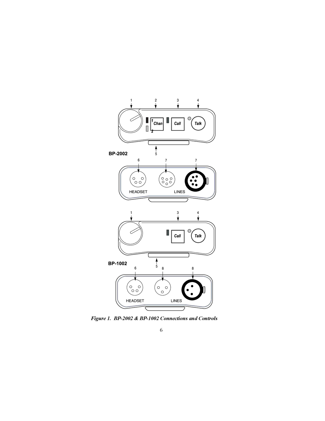
Figure 1.
BP-2002
&
BP-1002
Connections and Controls
6
Page 5
Page 7
Page 6
Image 6
Page 5
Page 7
Contents
Telex
Page
Introduction
End-User License Agreement for Telex Software
System Power
Initial BP-1002/BP-2002 Setup
BP-2002 & BP-1002 Connections and Controls
External Connections & Controls
Connections and Controls
Intercom Channel Connectors On the BP-2002
Operating Modes
Changing Modes of Operation
Internal SWITCHES, Jumpers and Adjustments
Side Tone Adjustment R145
Internal Switches and Jumpers
Connector PIN Configurations
Headset Connector
BP-2002
General
Interface Requirements
Headphone Amplifier
Dynamic Microphone Amplifier
Electret Microphone Amplifier
Board Number
Eliminating MIC-KILL and Call Signal
Restoring MIC-KILL and Call Signal
General Description
Printed Circuit Board
Factory Service
Top
Page
Image
Contents