Manuals
/
Telex
/
Computer Equipment
/
Network Card
Telex
BP-1002, BP-2002
operating instructions
Printed Circuit Board
Models:
BP-1002
BP-2002
1
21
23
23
Download
23 pages
56.05 Kb
16
17
18
19
20
21
22
23
Connector PIN Configurations
Initial BP-1002/BP-2002 Setup
Side Tone Adjustment R145
Factory Service
Internal Switches and Jumpers
Page 21
Image 21
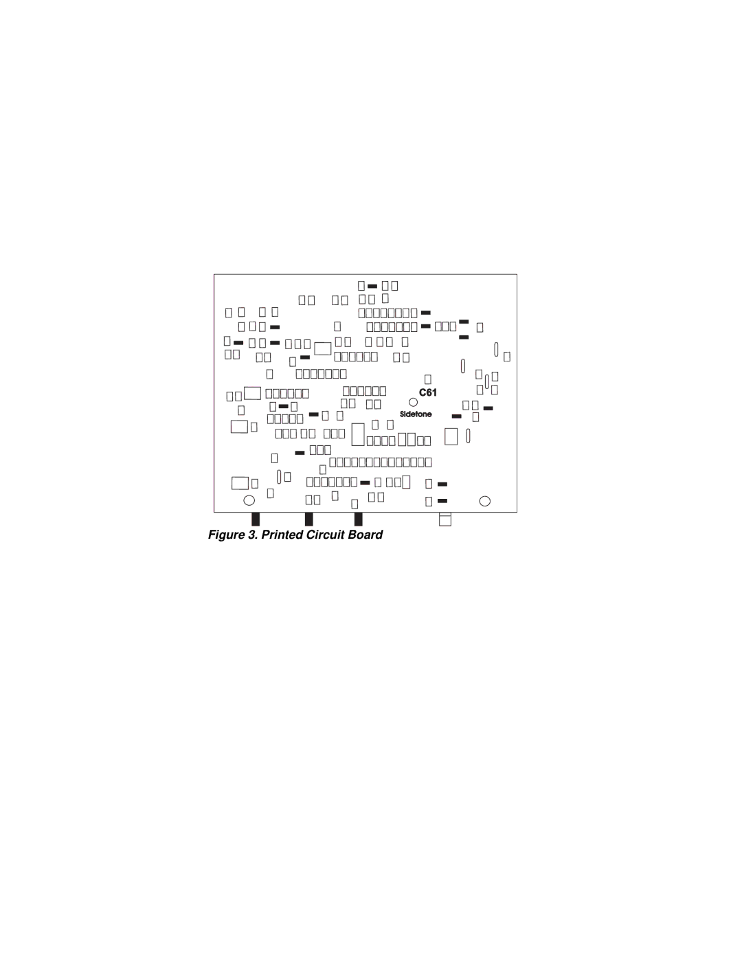
Figure 3. Printed Circuit Board
Page 20
Page 22
Page 21
Image 21
Page 20
Page 22
Contents
Telex
Page
Introduction
End-User License Agreement for Telex Software
Initial BP-1002/BP-2002 Setup
System Power
BP-2002 & BP-1002 Connections and Controls
Connections and Controls
External Connections & Controls
Intercom Channel Connectors On the BP-2002
Operating Modes
Changing Modes of Operation
Internal SWITCHES, Jumpers and Adjustments
Side Tone Adjustment R145
Internal Switches and Jumpers
Headset Connector
Connector PIN Configurations
BP-2002
Interface Requirements
General
Headphone Amplifier
Electret Microphone Amplifier
Dynamic Microphone Amplifier
Board Number
Eliminating MIC-KILL and Call Signal
Restoring MIC-KILL and Call Signal
General Description
Printed Circuit Board
Factory Service
Top
Page
Image
Contents