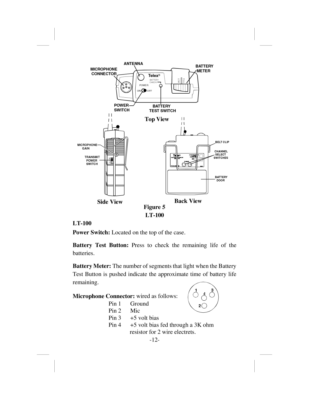
Top View
Side View | Back View |
| Figure 5 |
|
|
Power Switch: Located on the top of the case.
Battery Test Button: Press to check the remaining life of the batteries.
Battery Meter: The number of segments that light when the Battery Test Button is pushed indicate the approximate time of battery life remaining.
Microphone Connector: wired as follows:
Pin 1 | Ground |
Pin 2 | Mic |
Pin 3 | +5 volt bias |
Pin 4 | +5 volt bias fed through a 3K ohm |
| resistor for 2 wire electrets. |
|
