www.ti.com | Optional Configuration |
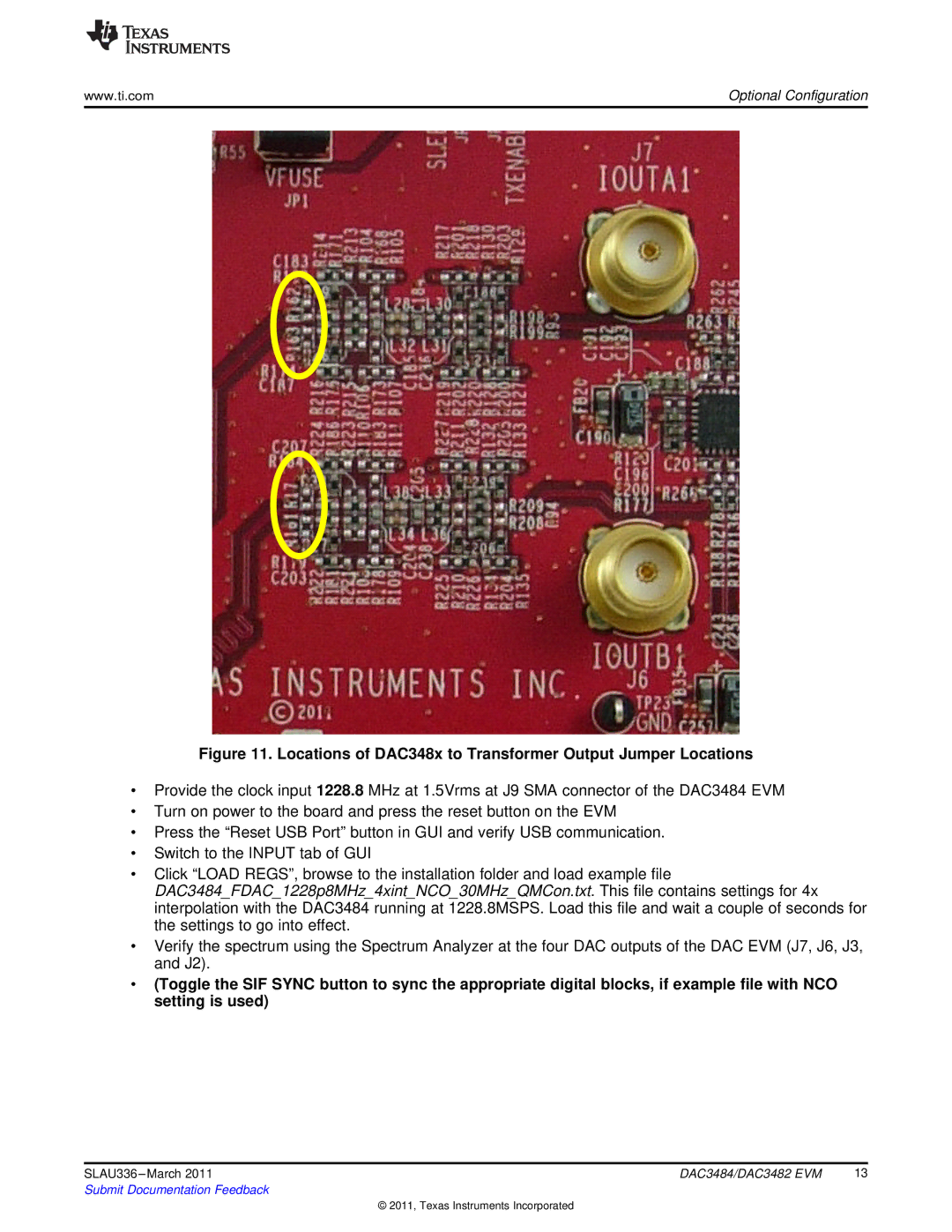
Figure 11. Locations of DAC348x to Transformer Output Jumper Locations
•Provide the clock input 1228.8 MHz at 1.5Vrms at J9 SMA connector of the DAC3484 EVM
•Turn on power to the board and press the reset button on the EVM
•Press the “Reset USB Port” button in GUI and verify USB communication.
•Switch to the INPUT tab of GUI
•Click “LOAD REGS”, browse to the installation folder and load example file
DAC3484_FDAC_1228p8MHz_4xint_NCO_30MHz_QMCon.txt. This file contains settings for 4x interpolation with the DAC3484 running at 1228.8MSPS. Load this file and wait a couple of seconds for the settings to go into effect.
•Verify the spectrum using the Spectrum Analyzer at the four DAC outputs of the DAC EVM (J7, J6, J3, and J2).
•(Toggle the SIF SYNC button to sync the appropriate digital blocks, if example file with NCO setting is used)
SLAU336 | DAC3484/DAC3482 EVM | 13 |
Submit Documentation Feedback |
|
|
© 2011, Texas Instruments Incorporated