Optional Configuration

www.ti.com

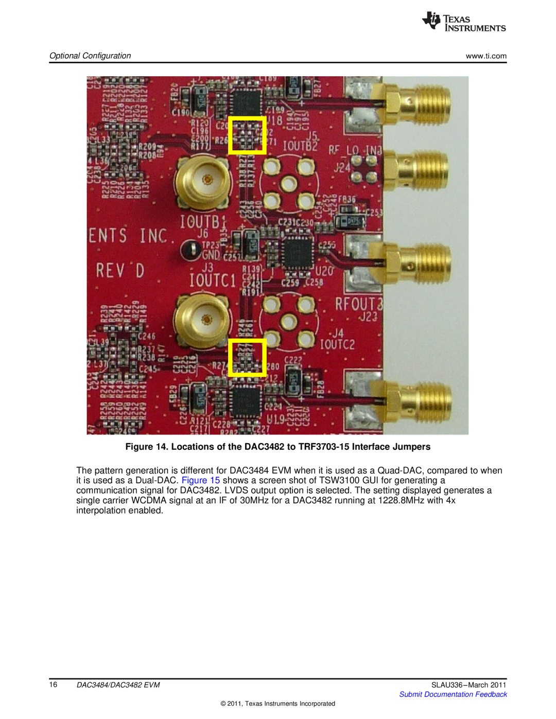
Figure 14. Locations of the DAC3482 to TRF3703-15 Interface Jumpers

The pattern generation is different for DAC3484 EVM when it is used as a Quad-DAC, compared to when it is used as a Dual-DAC. Figure 15 shows a screen shot of TSW3100 GUI for generating a communication signal for DAC3482. LVDS output option is selected. The setting displayed generates a single carrier WCDMA signal at an IF of 30MHz for a DAC3482 running at 1228.8MHz with 4x interpolation enabled.

16

DAC3484/DAC3482 EVM

SLAU336 –March 2011


Submit Documentation Feedback

© 2011, Texas Instruments Incorporated
Page 16
Image 16
Texas Instruments DAC3484 installation instructions Locations of the DAC3482 to TRF3703-15 Interface Jumpers