Users Guide
Submit Documentation Feedback
Contents
100
List of Figures
Side
List of Tables
Submit Documentation Feedback
About This Manual How to Use This Manual
Information About Cautions and Warnings
Related Documentation From Texas Instruments
Additional Documentation
If You Need Assistance FCC Warning
Trademarks
Description
Pin Assignments and Terminal Functions
Key Features
Introduction-PCM3793A/94A
Introduction-PCM3793A/94A
Pin Assignments and Terminal Functions
PCM3793A/94A Terminal Functions
DEM-DAI3793A/3794A EVM System Diagram
DEM-DAI3793A/3794A EVM Description
SBAU127 -July
Getting Started
Electrostatic Discharge Warning
Unpacking the EVM
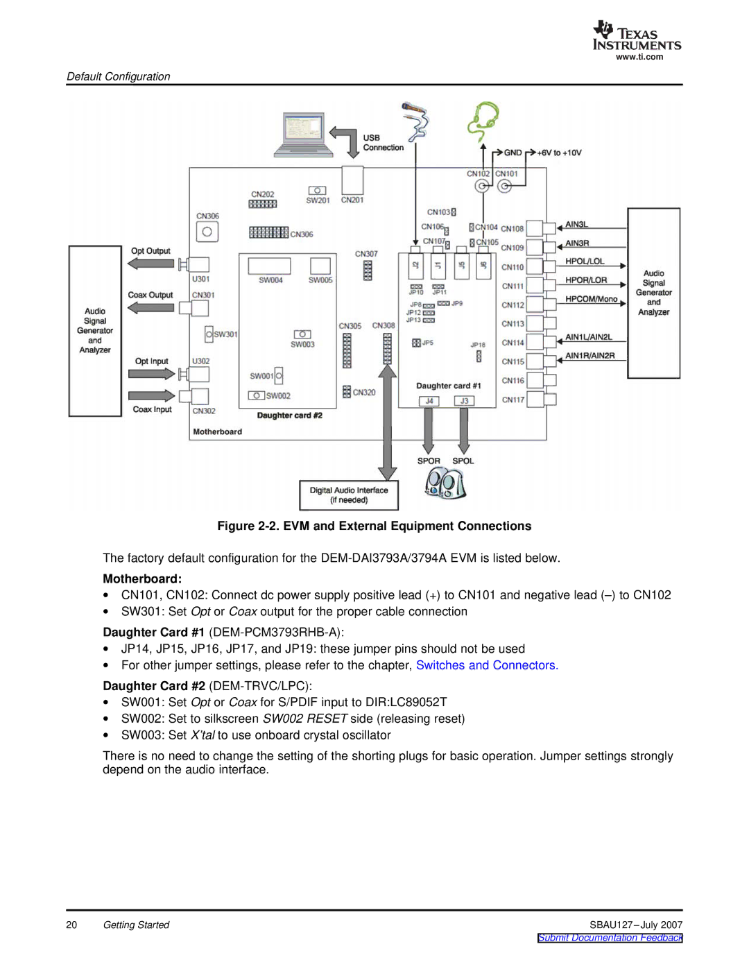
Default Configuration
EVM Configuration
Motherboard
Daughter Card #2 DEM-TRVC/LPC
Set-Up Guide
User Interface Panel
Basic Operating Set-Up
Software Control and Operation
Power On/Off Sequence
Module Function Controls
Power Up/Down
HP COM/MONO HPC
Power Up/Down Time ms Options
PCM3793A/94A Resistor 1257dh RES40 Resistor Value Control
Ramp Up Wave Form with Default
Setting Default Setting Record
Digital Out Mute Control Options
Gain Control for ADC Input Options
Digital Mute ATR Options
Playback
Playback Function Menu Tab
Headphone Gain Control Options
Speaker Gain Control Options
ALC Automatic Level Control
Digital Attenuation ATP Options
Auto Level Control Record Options
Signal Processing
Source Options
Output Options
Tone Control Options
3D Effect Options
Click Apply to Filter 1 or Apply to Filter
15. Notch Filter Characteristic Model
DAC Oversampling Control Options
Zero Cross Control Options
De-Emphasis Filter Options
High-Pass Filter Options
Analog Path
18. Analog Path Function Menu Tab
Analog Input Options
D2S Select Options
Analog Mixer Options
Mic Boost Options
Audio Interface Setting 1 Options
Audio Interface Setting 2 Options
PG5 Gain and PG6 Gain Options
Audio Interface
HP Detection Options
HP COM Short Detection Options
HP Short Detection, L-Ch HP Detection, R-Ch
Speaker Short Detection, L-Ch Speaker Short Detection, R-Ch
4 LC89052T DIR Digital Audio I/F Receiver Control Window
Digital Amplifier
Register Setting History
24. Register Setting History Window
Modifying a .csv File
25. Opening and Modifying a .csv File
Write function
Register Direct Access
Read function
Switches and Connectors
Daughter Card #2 DIR LC89052T and DIT DIT4096
Main Power Supply and Regulator
Power-Supply Terminals for PCM3793A Power-Supply Pins
Overview
Motherboard
Audio I/O
I/F Controller MSP430, TUSB3410
Daughter Card #1 PCM3793A
Analog Input and Output-Daughter Card #1
Analog Output Configuration Daughter Card #1
Audio Clock and Input Data Control Format-Daughter Card #2
Daughter Card #2 DIR LC89052T and DIT DIT4096
Analog Input and Output-Daughter Card #2
Evaluation and Measurements
Slave Mode With Audio Precision SYS-2722 Default Setting
Slave Mode Configuration With SYS-2722
Jumper Configuration for Slave Mode Default
Master Mode with Audio Precision SYS-2722
Master Mode Configuration With SYS-2722
Jumper Configuration for Master Mode
Combined Master and Slave Mode Configuration with SYS-2722
Combined Master and Slave Modes With PSIA-2722
Measurements for Dynamic Characteristics
Jumper Configuration for Combined Master and Slave Modes
Ω Headphone Output Inserted in Headphone Jack J6
Digital-to-Analog D/A Performance
D/A Line Output Parameters
Speaker Output Power Performance
Analog-to-Digital A/D Performance
A/D Line Input Parameters
Stereo Speaker Output Parameters
Speaker Output Filter Configuration
LC Low-Pass Filter
Result BPZ Zero Data Input Result -60dB Input
Amplitude Versus Frequency Performance
4.1 A/D Spectrum
4.2 D/A Spectrum
11. D/A Amplitude vs Frequency
Connection Diagram for Practical Applications
PCM3793A/94A
Filter Consideration for Speaker Output
16. Recommended Ferrite Bead Filter for Speaker Output
Schematic, PCB Layout, and Bill of Materials
Schematics
PCM3793A DEM-PCM3793RHB-A Connector Daughter Card #1
PCM3793A DEM-PCM3793RHB-A Daughter Card #1
Printed Circuit Board Layout
PCM3793A DEM-PCM3793RHB-A Board Layout-Silkscreen Side
PCM3793A DEM-PCM3793RHB-A Board Layout-Component Side
PCM3793A DEM-PCM3793RHB-A Board Layout-Inner Layer
PCM3793A DEM-PCM3793RHB-A Board Layout-Inner Layer
PCM3793A DEM-PCM3793RHB-A Board Layout-Solder Side
Component List
Bill of Materials
Submit Documentation Feedback
Appendix a
Reference .csv Files
Table A-1. .csv Files
Related Signal Flow Diagrams
Figure A-1. Line Output and Headphone Output
Figure A-2. Headphone Output with Sound Effect
Figure A-3. Cap-Less Headphone Output
Figure A-4. Headphone Output with Line Input AIN2L/AIN2R
0dB
AIN3L MUX1 AIN2L AIN1L D2S AIN1R MUX2 AIN3R AIN2R
Figure A-7. Stereo Speaker Output
Figure A-8. Mono Speaker Output
Figure A-9. Speaker Output with Line Input AIN2L/AIN2R
Figure A-10. Speaker Output with Mono Mic Input AIN1L, +20dB
+20dB
Figure A-12. Line Input AIN2L/AIN2R to Headphone Output
Figure A-13. Mono Line Input AIN2L to Headphone Output
Figure A-14. Mono Mic Input AIN1L, +20dB to Headphone Output
+20dB
Figure A-16. Mono Mic Input AIN1L, +20dB to Speaker Output
Figure A-17. Line Input AIN3L/AIN3R
Figure A-18. Mic Input AIN1L/AIN1R, +20dB
Figure A-19. Mic Input AIN1L/AIN1R, +20dB with ALC
Figure A-20. Mono Mic Input AIN1L, +20dB
Figure A-21. Mono Mic Input AIN1L, +20dB with ALC
Figure A-22. Mono Diff Mic Input AIN1L/AIN1R, +20dB
Figure A-23. Mono Diff Mic Input AIN1L/AIN1R, +20dB with ALC
Figure A-24. Slave Mode Operation
Interfacing to DSPs
Package Information
Table A-2. Recommended Power-On Sequence for PCM3793A
Register Control with DSP Interface
Evaluation BOARD/KIT Important Notice
FCC Warning
Important Notice