Interface Assignments
3.1 Interface Assignments
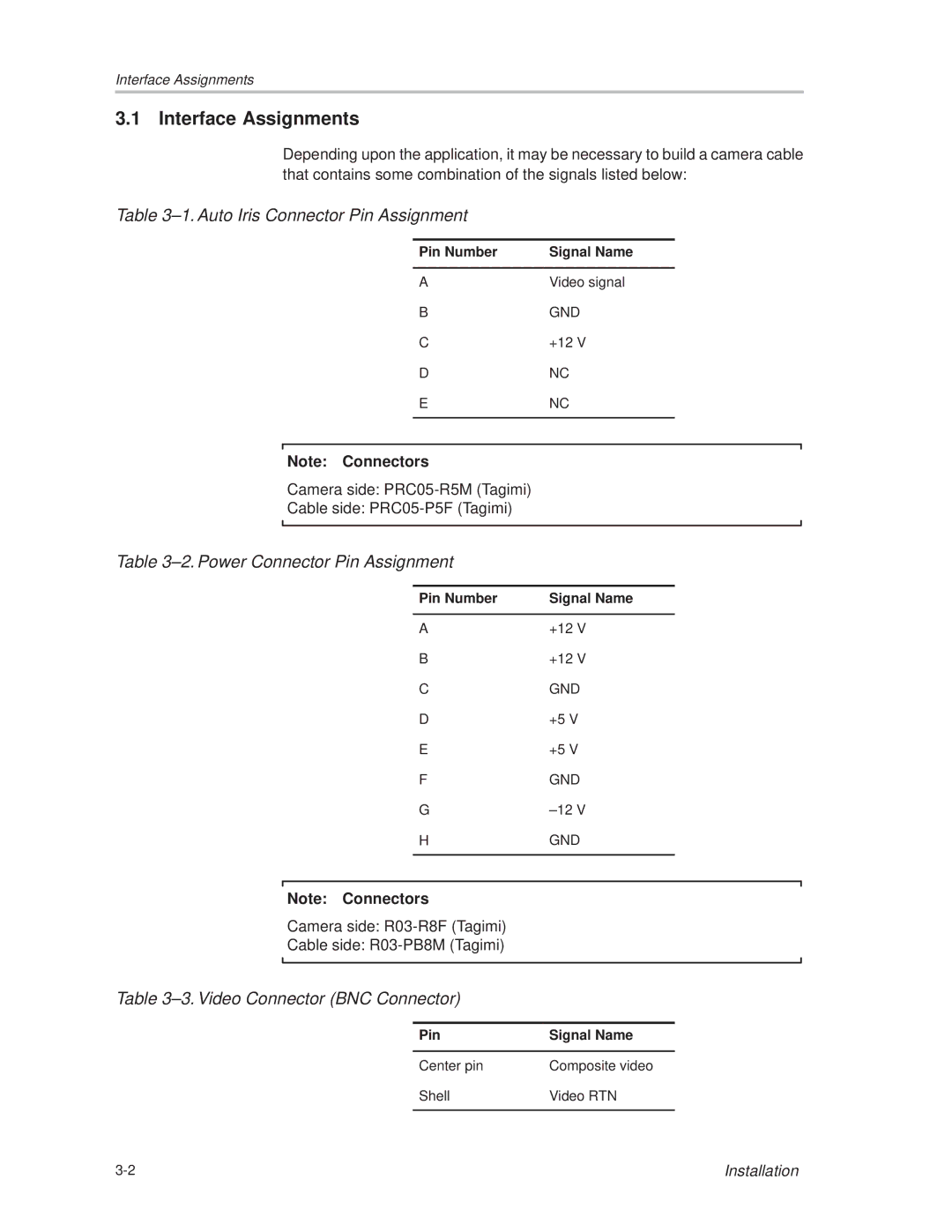
Depending upon the application, it may be necessary to build a camera cable that contains some combination of the signals listed below:
Table 3±1. Auto Iris Connector Pin Assignment
Pin Number | Signal Name |
|
|
A | Video signal |
B | GND |
C | +12 V |
D | NC |
E | NC |
|
|
Note: Connectors
Camera side:
Cable side:
Table 3±2. Power Connector Pin Assignment
Pin Number | Signal Name |
|
|
A | +12 V |
B | +12 V |
C | GND |
D | +5 V |
E | +5 V |
F | GND |
G | ±12 V |
H | GND |
|
|
Note: Connectors
Camera side:
Cable side:
Table 3±3. Video Connector (BNC Connector)
Pin | Signal Name |
|
|
Center pin | Composite video |
Shell | Video RTN |
|
|
Installation |