Default Jumper Positioins
2.3 Default Jumper Positioins
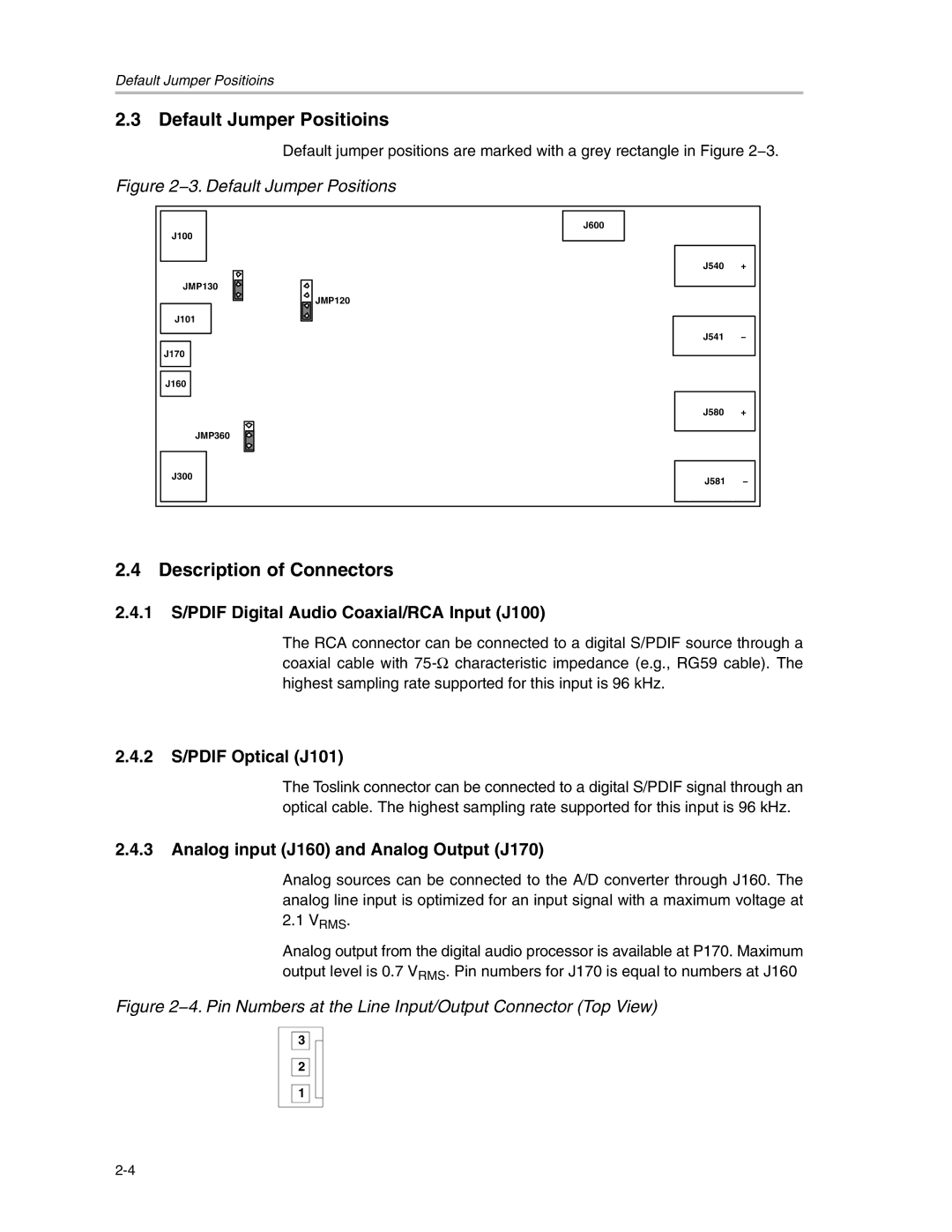
Default jumper positions are marked with a grey rectangle in Figure 2−3.
Figure 2−3. Default Jumper Positions
J100
JMP130
J101
J170
J160
JMP120
J600
J540 +
J541 −
| J580 | + |
| JMP360 |
|
J300 | J581 | − |
|
2.4 Description of Connectors
2.4.1S/PDIF Digital Audio Coaxial/RCA Input (J100)
The RCA connector can be connected to a digital S/PDIF source through a coaxial cable with
2.4.2S/PDIF Optical (J101)
The Toslink connector can be connected to a digital S/PDIF signal through an optical cable. The highest sampling rate supported for this input is 96 kHz.
2.4.3Analog input (J160) and Analog Output (J170)
Analog sources can be connected to the A/D converter through J160. The analog line input is optimized for an input signal with a maximum voltage at
2.1VRMS.
Analog output from the digital audio processor is available at P170. Maximum output level is 0.7 VRMS. Pin numbers for J170 is equal to numbers at J160
Figure 2−4. Pin Numbers at the Line Input/Output Connector (Top View)
3 ![]()
![]()
2
1