Description of Connectors
2.4.5Loudspeaker Connectors (J540, J541, J580, and J581)
All speaker connectors accept standard 4 mm plugs. Use of high quality plugs and speaker cable are recommended.
Table 2−3. Description of Loudspeaker Connectors
Reference Designator | Description |
J540 | Left speaker positive output terminal |
|
|
J541 | Left speaker negative output terminal |
|
|
J580 | Right speaker positive output terminal |
|
|
J581 | Right speaker negative output terminal |
Caution
Both positive and negative speaker outputs are floating and may NOT be connected to ground (f.ex. through an oscilloscope).
2.4.6Power Supply Connector
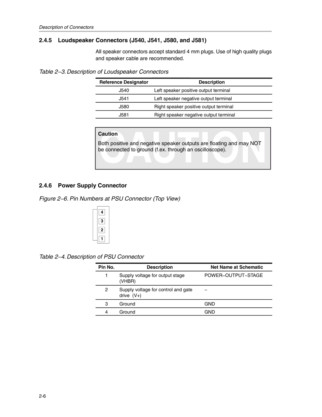
Figure 2−6. Pin Numbers at PSU Connector (Top View)
4
3
2
1
Table 2−4. Description of PSU Connector
Pin No. | Description | Net Name at Schematic |
1 | Supply voltage for output stage | POWER−OUTPUT−STAGE |
| (VHBR) |
|
|
|
|
2 | Supply voltage for control and gate | − |
| drive (V+) |
|
|
|
|
3 | Ground | GND |
|
|
|
4 | Ground | GND |