Jumper Settings

3.2 Jumper Settings

There are two jumpers on the EVM.

-JP1 is used to select the communication mode of the EVM. Position 1–2 sets the mode for SPI. Position 2–3 sets the mode for I2C. The GUI software was developed for I2C communication. For SPI the end-user needs to create the necessary code. Signals needed for SPI are available on the EVM.

-JP2 is used to select or deselect the onboard crystal for MASTER CLOCK.

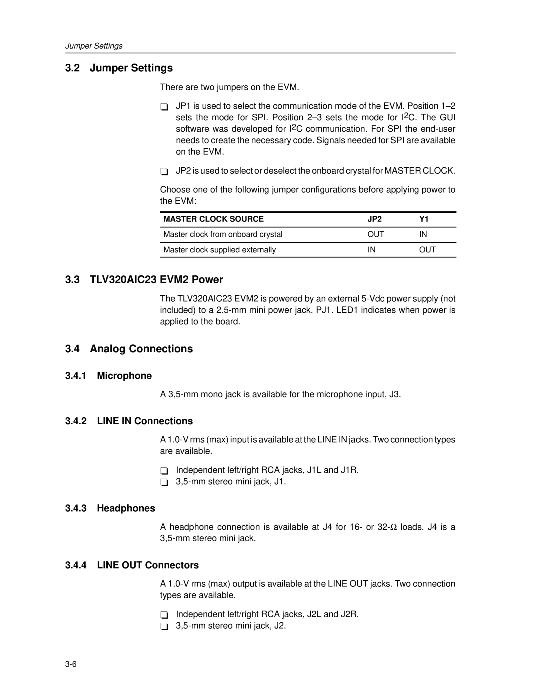
Choose one of the following jumper configurations before applying power to the EVM:

MASTER CLOCK SOURCE

JP2

Y1


Master clock from onboard crystal

OUT

IN


Master clock supplied externally

IN

OUT


3.3 TLV320AIC23 EVM2 Power

The TLV320AIC23 EVM2 is powered by an external 5-Vdc power supply (not included) to a 2,5-mm mini power jack, PJ1. LED1 indicates when power is applied to the board.

3.4 Analog Connections

3.4.1Microphone

A 3,5-mm mono jack is available for the microphone input, J3.

3.4.2LINE IN Connections

A 1.0-V rms (max) input is available at the LINE IN jacks. Two connection types are available.

-Independent left/right RCA jacks, J1L and J1R.

-3,5-mm stereo mini jack, J1.

3.4.3Headphones

A headphone connection is available at J4 for 16- or 32-loads. J4 is a 3,5-mm stereo mini jack.

3.4.4LINE OUT Connectors

A 1.0-V rms (max) output is available at the LINE OUT jacks. Two connection types are available.

-Independent left/right RCA jacks, J2L and J2R.

-3,5-mm stereo mini jack, J2.

3-6

Page 18
Image 18
Texas Instruments TLV320DAC23 manual Jumper Settings, TLV320AIC23 EVM2 Power, Analog Connections