Sampling Rate Register
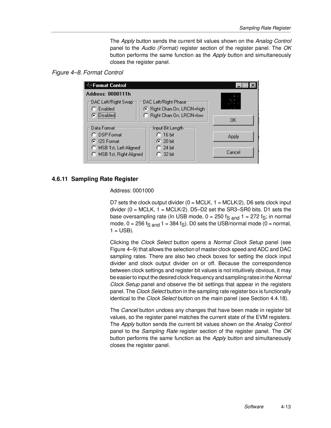
The Apply button sends the current bit values shown on the Analog Control panel to the Audio (Format) register section of the register panel. The OK button performs the same function as the Apply button and simultaneously closes the register panel.
Figure 4–8. Format Control
4.6.11Sampling Rate Register
Address: 0001000
D7 sets the clock output divider (0 = MCLK, 1 = MCLK/2), D6 sets clock input divider (0 = MCLK, 1 = MCLK/2).
mode, 0 = 256 fS and 1 = 384 fS). D0 sets the USB/normal mode (0 = normal, 1 = USB).
Clicking the Clock Select button opens a Normal Clock Setup panel (see Figure
The Cancel button undoes any changes that have been made in register bit values, so the register panel matches the current state of the EVM registers. The Apply button sends the current bit values shown on the Analog Control panel to the Sampling Rate register section of the register panel. The OK button performs the same function as the Apply button and simultaneously closes the register panel.
Software
