I2C Adjust
4.4.18Clock Select Button
Clicking the Clock Select button opens a panel that allows selection of master clock speed and ADC and DAC sampling rates (see Section 4.6.11). (Do clock selections correspond to sampling rate register bits?)
4.4.19 Frequency Display Areas
In the lower right corner of the main panel are two frequency displays. The one on the left shows the master clock frequency MCLK in megaHertz; the one on the right shows the DAC sampling frequency in kiloHertz.
4.5 I2C Adjust
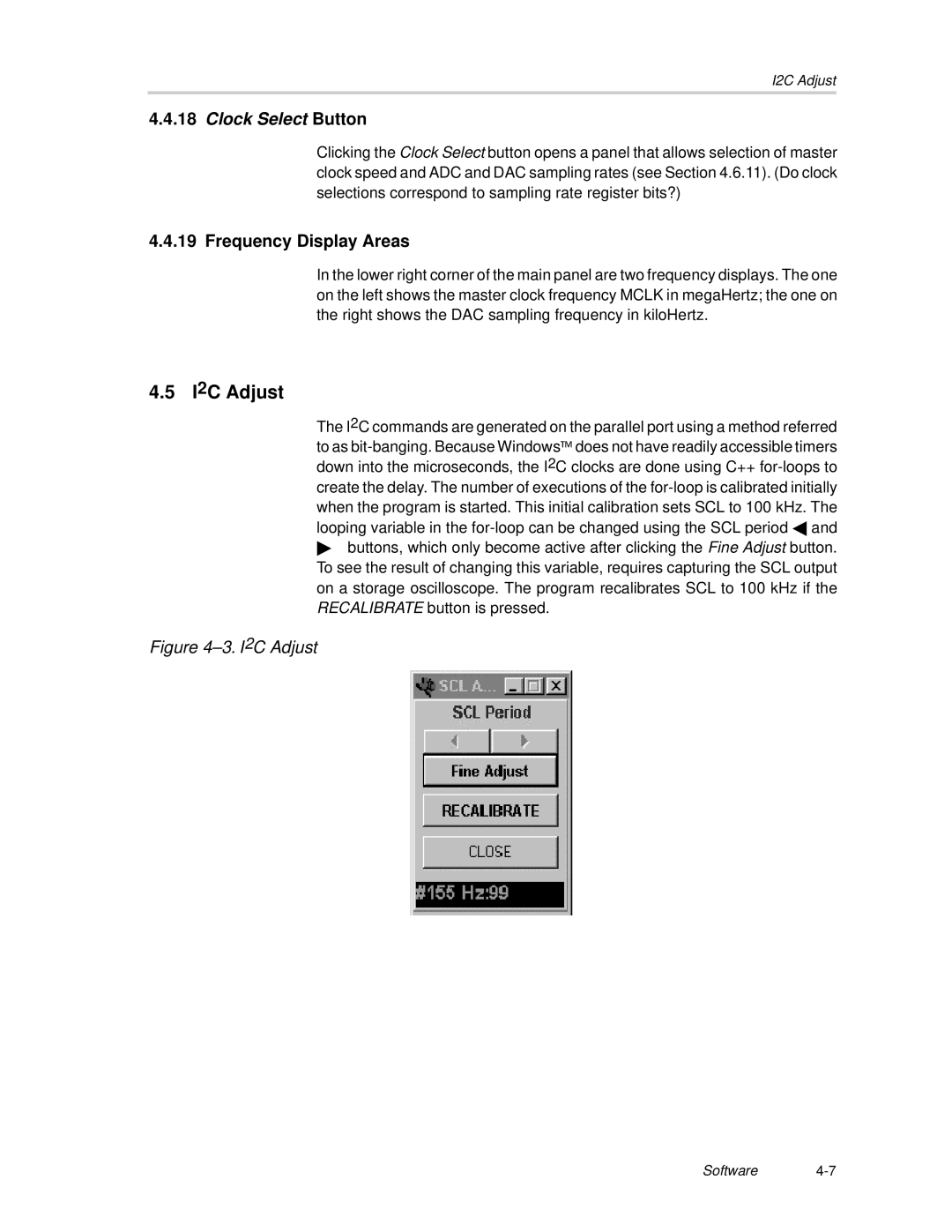
The I2C commands are generated on the parallel port using a method referred to as
"buttons, which only become active after clicking the Fine Adjust button. To see the result of changing this variable, requires capturing the SCL output on a storage oscilloscope. The program recalibrates SCL to 100 kHz if the RECALIBRATE button is pressed.
Figure 4–3. I2C Adjust
Software4-7
