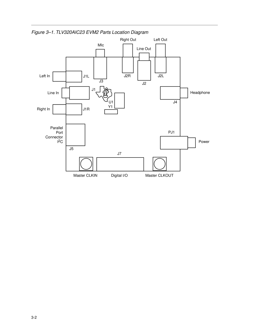
Manuals
/
Brands
/
Communications
/
Conference Phone
/
Texas Instruments
/
Communications
/
Conference Phone
Texas Instruments
TLV320AIC23, TLV320DAC23
Figure 31.TLV320AIC23 EVM2 Parts Location Diagram
1
14
47
47
Download
47 pages, 1.02 Mb
3-2
Figure 3
–
1.TLV320AIC23 EVM2 Parts Location Diagram
Headphone
Left In
J2
J2R J2L
U1
Y1
J3
J1L
J1
J1R
J5
Master CLKIN
J7
PJ1
J4
Left Out
Right Out
Line Out
MIc
Right In
Line In
Parallel
Port
Connector
I
2
C
Master CLKOUT
Digital I/O
Power
Contents
Main
Page
Page
Page
Preface
Read This First
About This Manual
How to Use This Manual
Related Documentation From Texas Instruments
FCC Warning
Trademarks
Contents
Figures
Chapter 1
Introduction
Page
Chapter 2
Quick Start-Up
Page
Theory of Operation
Figure 31.TLV320AIC23 EVM2 Parts Location Diagram
Page
Page
Page
3.2 Jumper Settings
3.3 TLV320AIC23 EVM2 Power
3.4 Analog Connections
3.4.1 Microphone
3.4.2 LINE IN Connections
3.5 Digital I/O
3.6 TLV320AIC23 EVM2 Features
3.6.1 Master Clock
3.6.2 Digital Loopback
3.6.3 Software Interface Connection
Page
Chapter 4
Software
Topic Page
4.1 DASCCT_AIC23 Installation
Figure 41.AIC23/DAC23 EVM2 Connection Diagram
4.2 DASCCT_AIC23 Start-Up
4.3 DASCCT_AIC23 Overview
4.4 Main Panel
Figure 42.Main Panel
4.4.1 About Button
4.4.4 Message Area
4.4.5 Line Input Volume
4.4.6 HeadPhone Volume
4.4.7 RESET Button
4.4.8 EXIT Button
Page
4.4.18 Clock Select Button
4.4.19 Frequency Display Areas
Figure 43.I 2C Adjust
4.5 I2C Adjust
4.6 View Registers
Figure 44.Register GUI
4.6.1 Preset Modes
Page
4.6.2 L Vol (Line Input) Register
4.6.3 R Vol (Line Input) Register
4.6.4 L Vol (HeadPhone) Register
4.6.5 R Vol (HeadPhone) Register
4.6.6 OK, Apply, and Cancel Buttons
Figure 46.Analog Control
4.6.8 Audio (Digital) Register
Figure 47.Digital Control
4.6.9 Power Down Register
4.6.10 Audio (Format) Register
Figure 48.Format Control
4.6.11 Sampling Rate Register
Page
Chapter 5
I2C Error Messages
Page
Kit Contents
6.1 TLV320AIC23 EVM2 Kit Contents
6.2 Bill of Materials