FOR HVAC INSTALLER ONLY
5.DEH 3000 Digital Control Installation Instructions
Control Part No. 4026570 | |
5.1 Specifications |
|
Part # (P/N) | 4026570 |
Model: | DEH 3000 Digital Control |
Electrical: | 24 VAC |
Humidity Range: | 10 – 95% RH |
Humidity Accuracy: | +/- 5% |
Output: | 3 Amps 24 VAC |
Relay Capacity | 5 Amps |
Temp Range/Accuracy | 2% |
Size | 4.95" wide x 4.19" high |
FOR HVAC INSTALLER ONLY:
5.2 Installation
This control panel must be installed in the conditioned space and in accordance with all applicable codes and standards. Follow the instructions below when installing and setting this control.
5.2A Install Instructions
1.Separate the front panel from the back panel by depressing the middle sections of the top and bottom of the front panel.
2.Line the back panel up against the wall or flat surface onto which it is to be mounted and drill in the appropriate mounting holes.
3.Insert the screws and tighten down so they extend approximately 1/8” from the back plate.
4.Align the back panel so that the control is level.
5.Tighten the screws to lock into position.
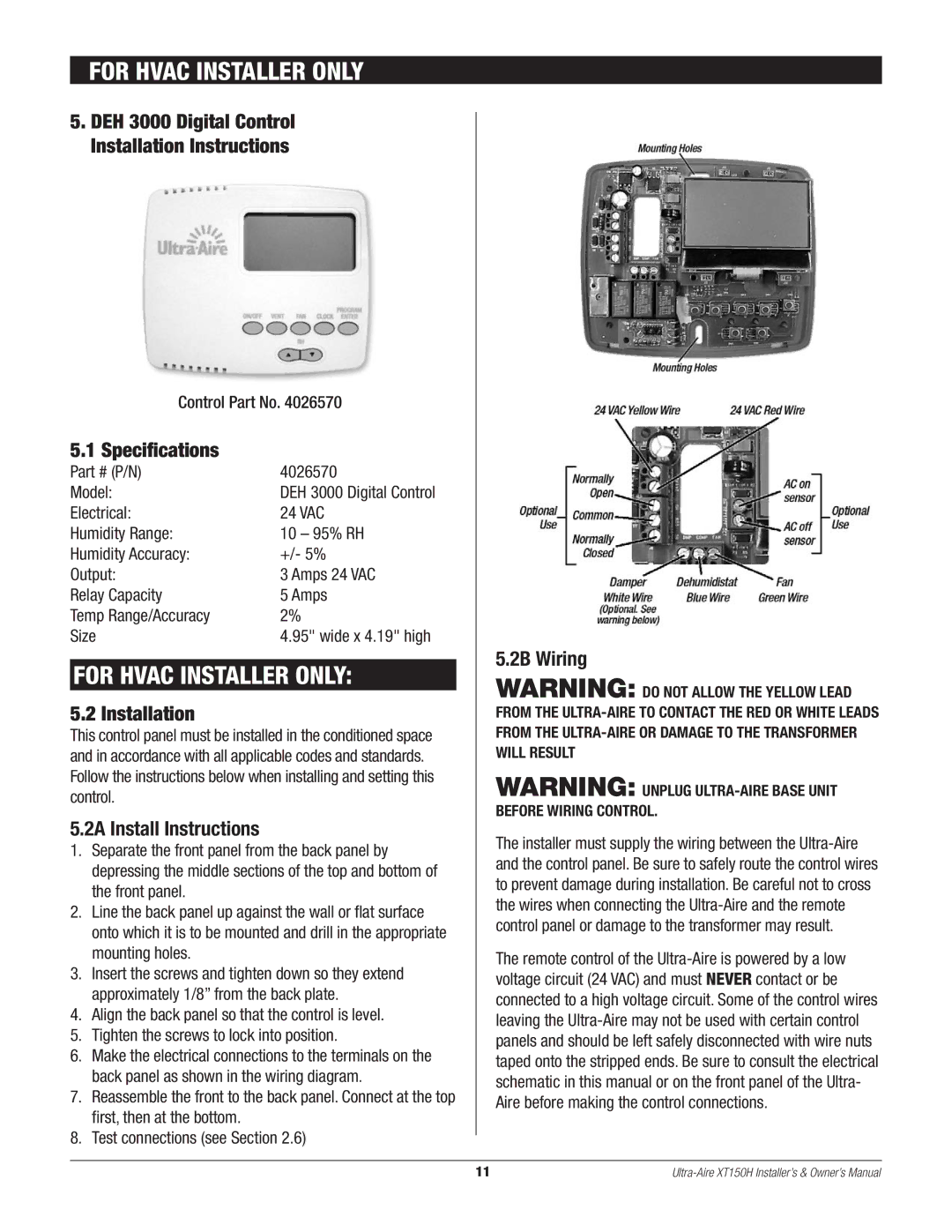
6.Make the electrical connections to the terminals on the back panel as shown in the wiring diagram.
7.Reassemble the front to the back panel. Connect at the top first, then at the bottom.
8.Test connections (see Section 2.6)
5.2B Wiring
WARNING: DO NOT ALLOW THE YELLOW LEAD FROM THE
WARNING: UNPLUG
The installer must supply the wiring between the
The remote control of the
11 |
