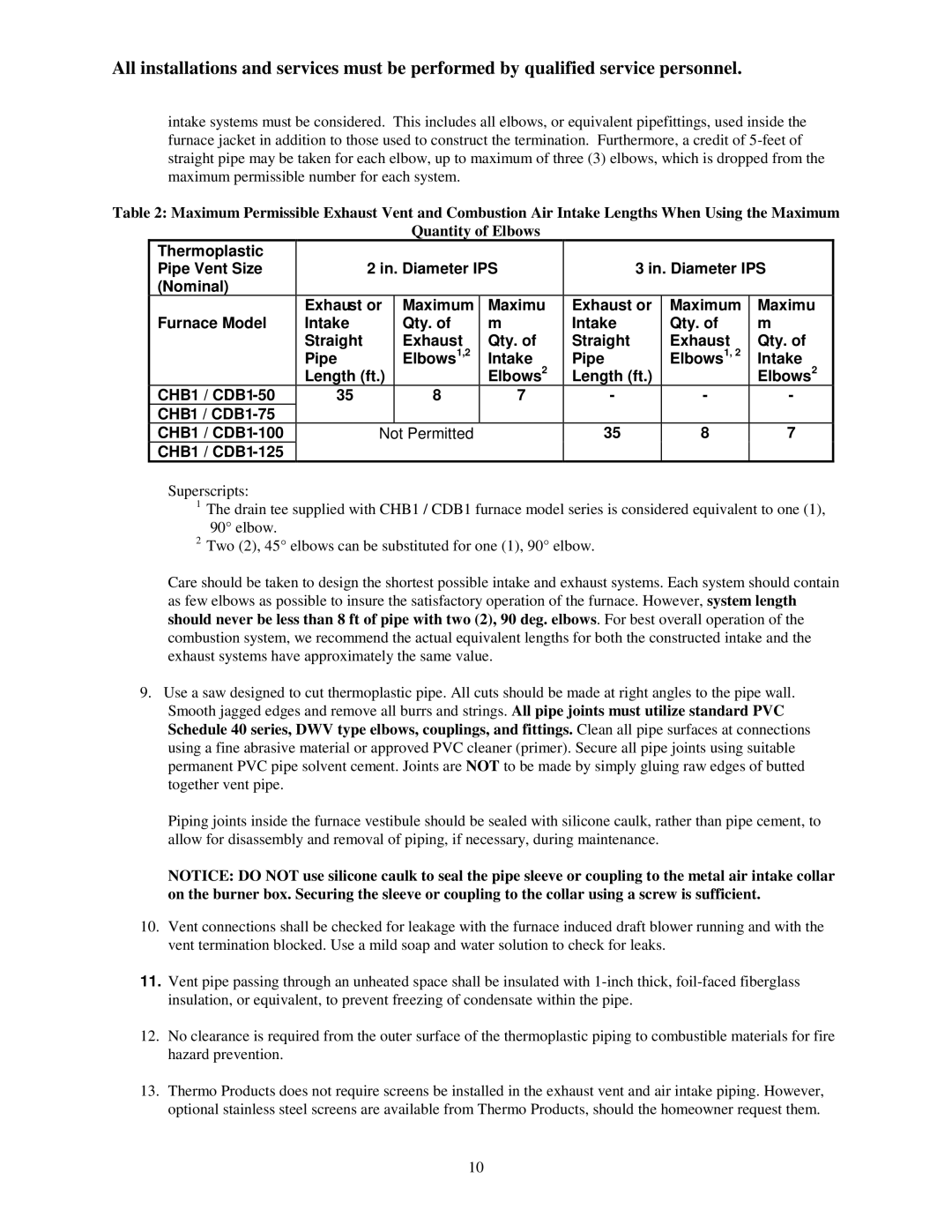
CHB1-50N, CBD1-50N, CBD1-125N, CBD1-100N, CBD1-75N specifications
Thermo Products offers a range of high-performance heating and cooling solutions tailored to meet the demands of both residential and commercial applications. Among their innovative offerings are the CHB1-50N, CBD1-75N, CHB1-100N, CHB1-125N, and CBD1-100N models, which are designed to provide efficient temperature control while maximizing energy savings.The CHB1 series, including the CHB1-50N, CHB1-100N, and CHB1-125N, features advanced heating technologies that allow for rapid heating response times. These units are equipped with high-efficiency heat exchangers that ensure optimal heat transfer with minimal energy consumption. A key characteristic of these models is their ability to operate quietly, making them ideal for settings where noise reduction is a priority.
In comparison, the CBD1 series, specifically the CBD1-75N and CBD1-100N, focuses on cooling capabilities that are equally impressive. These units utilize state-of-the-art cooling compressors designed to provide powerful cooling while maintaining low operational costs. The CBD1 models incorporate environmentally friendly refrigerants, ensuring compliance with the latest environmental regulations, which appeals to environmentally conscious customers.
All models in this lineup are designed with user friendliness in mind, featuring intuitive digital controls that allow for precise temperature adjustments. This makes them suitable for end users with varying levels of technical expertise. Additionally, the units support smart home integration, enabling remote monitoring and control via mobile apps, which enhances comfort and convenience for users.
Durability is another hallmark of Thermo Products. The robust construction of both the CHB1 and CBD1 series units ensures resilience against harsh weather conditions and prolonged usage. Furthermore, they come equipped with advanced safety features, including over-temperature protection and automatic shut-off mechanisms, which provide peace of mind for consumers.
In summary, the Thermo Products CHB1-50N, CBD1-75N, CHB1-100N, CHB1-125N, and CBD1-100N models represent a comprehensive solution for effective heating and cooling needs. With their blend of efficiency, innovative technologies, user-friendly design, and durability, these products are positioned to deliver exceptional value and performance in a variety of environments.
