TOA Electronics EX-16 manual System Block Diagram

Models: EX-16

1 36
Download 36 pages 18.9 Kb
Page 8
Image 8

(e)Integral Terminal for Connecting Stations

The connection terminal for the exchange and stations is built into the exchange and connected to each LAU with a mother board.

(Wiring of the terminal and the station will be explained in a separate section.)

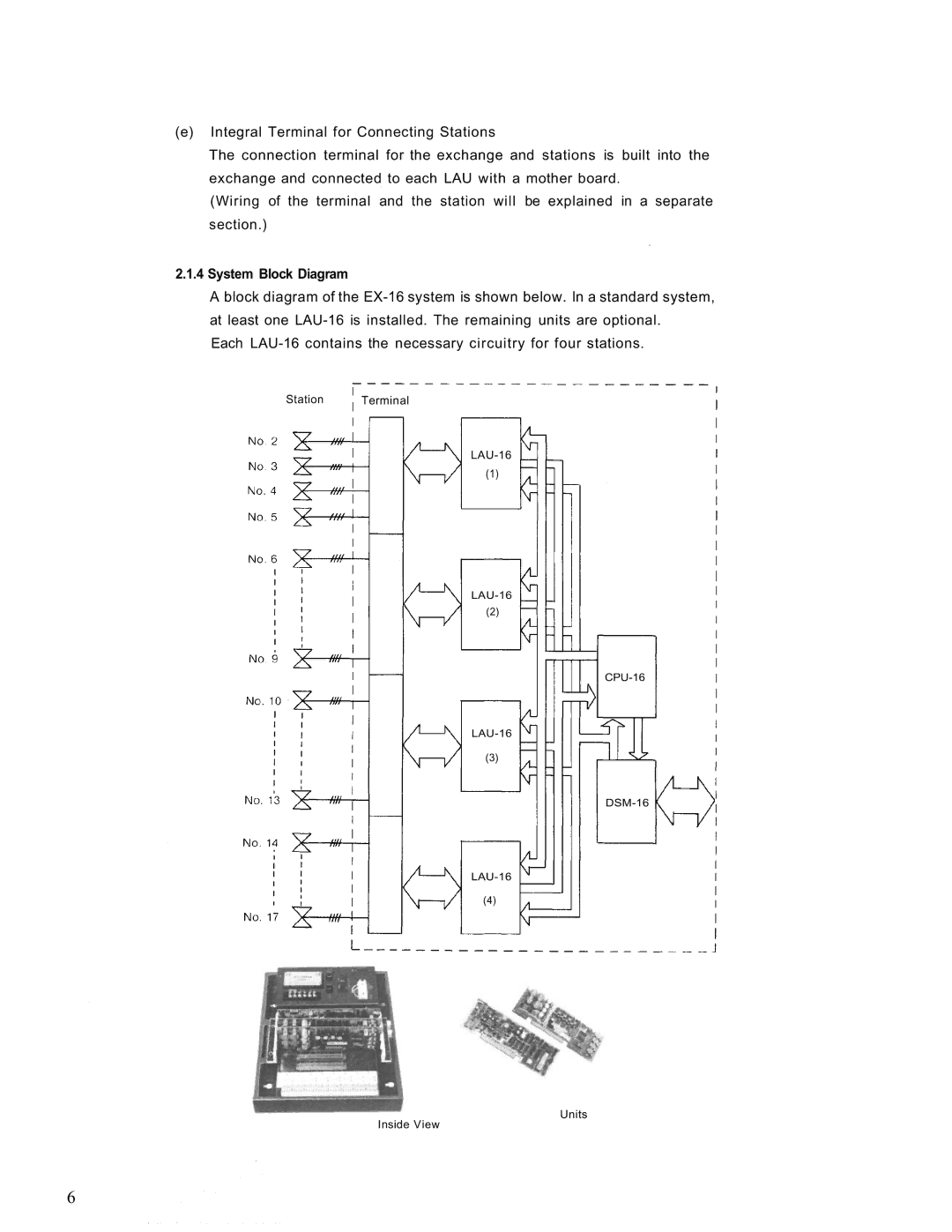
2.1.4System Block Diagram

A block diagram of the EX-16 system is shown below. In a standard system,

at least one LAU-16 is installed. The remaining units are optional. Each LAU-16 contains the necessary circuitry for four stations.

Station Terminal

LAU-16

(1)

LAU-16

(2)

CPU-16

LAU-16

(3)

DSM-16

LAU-16

(4)

Units

Inside View

6

Page 8
Image 8
TOA Electronics EX-16 manual System Block Diagram