12 Setup
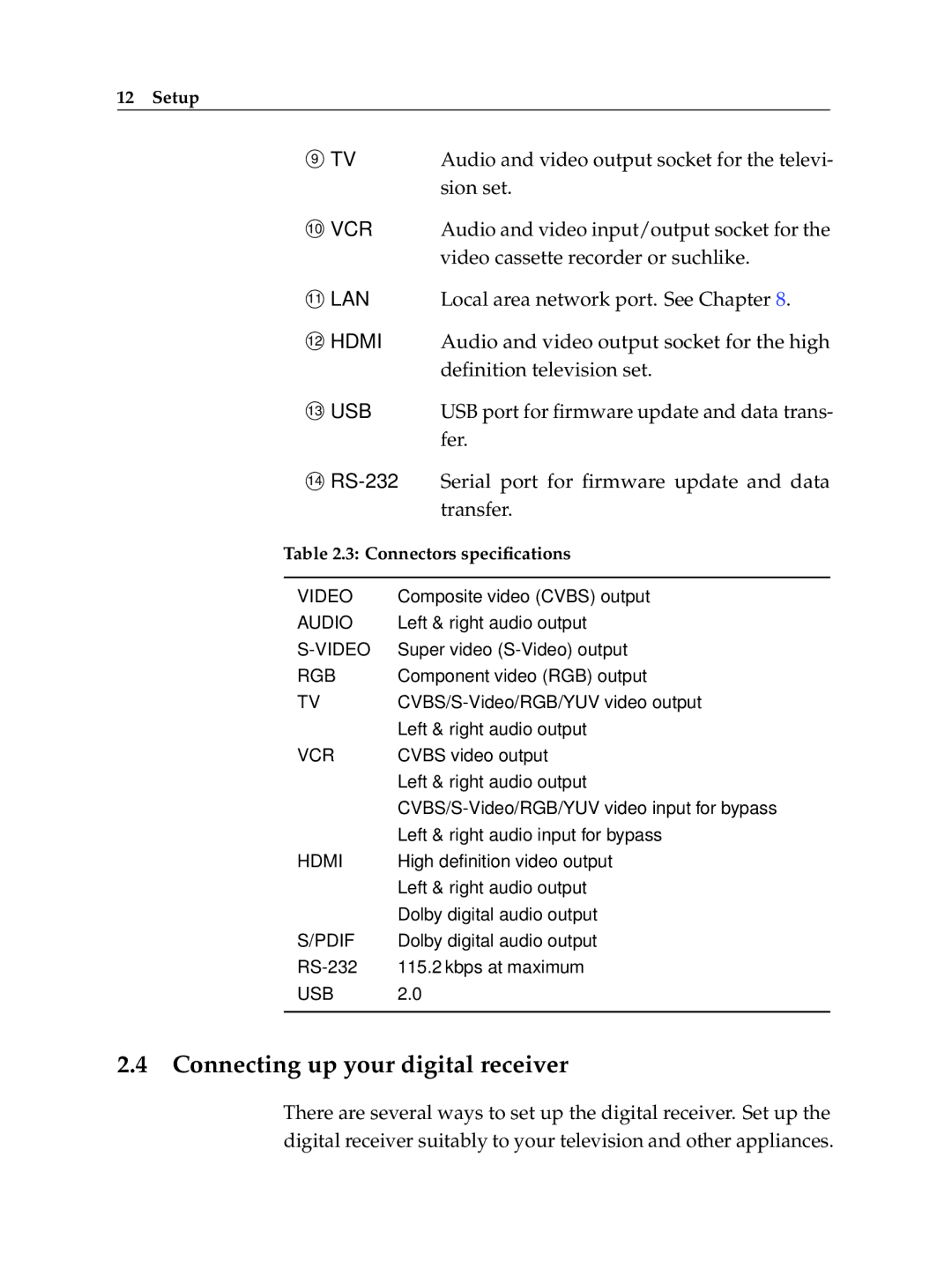
TV |
| Audio and video output socket for the televi- | |
9 |
|
|
|
|
| sion set. | |
VCR |
| Audio and video input/output socket for the | |
10 |
|
|
|
|
| video cassette recorder or suchlike. | |
LAN |
| Local area network port. See Chapter 8. | |
11 |
|
|
|
HDMI |
| Audio and video output socket for the high | |
12 |
|
|
|
|
| definition television set. | |
USB |
| USB port for firmware update and data trans- | |
13 |
|
|
|
|
| fer. | |
| Serial port for firmware update and data | ||
14 |
|
|
|
|
| transfer. | |
Table 2.3: Connectors specifications | |||
|
|
| |
VIDEO | Composite video (CVBS) output | ||
AUDIO | Left & right audio output | ||
Super video | |||
RGB | Component video (RGB) output | ||
TV | |||
| Left & right audio output | ||
VCR | CVBS video output | ||
| Left & right audio output | ||
| |||
| Left & right audio input for bypass | ||
HDMI | High definition video output | ||
| Left & right audio output | ||
| Dolby digital audio output | ||
S/PDIF | Dolby digital audio output | ||
115.2 kbps at maximum | |||
USB | 2.0 |
|
|
|
|
|
|
2.4Connecting up your digital receiver
There are several ways to set up the digital receiver. Set up the digital receiver suitably to your television and other appliances.
