TOSHIBA
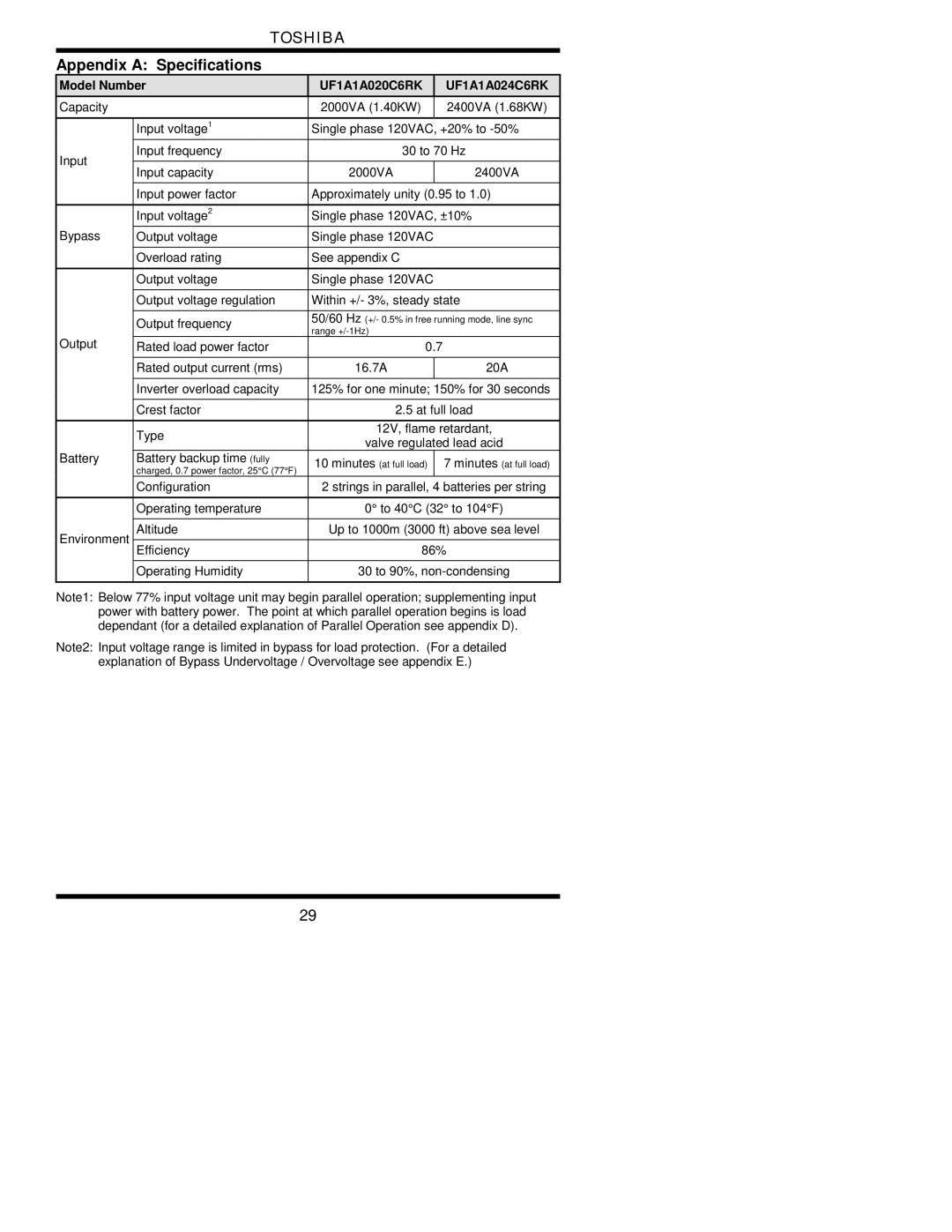
Appendix A: Specifications
| Model Number | UF1A1A020C6RK |
| UF1A1A024C6RK | |
| Capacity |
| 2000VA (1.40KW) |
| 2400VA (1.68KW) |
|
|
|
|
| |
|
| Input voltage1 | Single phase 120VAC, +20% to | ||
|
|
|
| ||
| Input | Input frequency | 30 to 70 Hz | ||
|
|
|
|
| |
| Input capacity | 2000VA |
| 2400VA | |
|
|
| |||
|
|
|
|
| |
|
| Input power factor | Approximately unity (0.95 to 1.0) | ||
|
|
|
| ||
|
| Input voltage2 | Single phase 120VAC, ±10% | ||
| Bypass |
|
|
| |
| Output voltage | Single phase 120VAC |
| ||
|
|
|
|
| |
|
| Overload rating | See appendix C |
| |
|
|
|
|
| |
|
| Output voltage | Single phase 120VAC |
| |
|
|
|
| ||
|
| Output voltage regulation | Within +/- 3%, steady state | ||
|
|
|
| ||
|
| Output frequency | 50/60 Hz (+/- 0.5% in free running mode, line sync | ||
|
| range |
| ||
|
|
|
| ||
| Output | Rated load power factor | 0.7 |
| |
|
|
|
|
| |
|
| Rated output current (rms) | 16.7A |
| 20A |
|
|
|
|
| |
|
| Inverter overload capacity | 125% for one minute; 150% for 30 seconds | ||
|
|
|
| ||
|
| Crest factor | 2.5 at full load | ||
|
|
|
| ||
|
| Type | 12V, flame retardant, | ||
|
| valve regulated lead acid | |||
|
|
| |||
| Battery | Battery backup time (fully | 10 minutes (at full load) |
| 7 minutes (at full load) |
|
| charged, 0.7 power factor, 25°C (77°F) |
| ||
|
|
|
|
| |
|
| Configuration | 2 strings in parallel, 4 batteries per string | ||
|
|
|
| ||
|
| Operating temperature | 0° to 40°C (32° to 104°F) | ||
|
|
|
| ||
| Environment | Altitude | Up to 1000m (3000 ft) above sea level | ||
|
|
|
|
| |
| Efficiency | 86% | |||
|
| ||||
|
|
|
| ||
|
| Operating Humidity | 30 to 90%, | ||
|
|
|
|
|
|
Note1: Below 77% input voltage unit may begin parallel operation; supplementing input power with battery power. The point at which parallel operation begins is load dependant (for a detailed explanation of Parallel Operation see appendix D).
Note2: Input voltage range is limited in bypass for load protection. (For a detailed explanation of Bypass Undervoltage / Overvoltage see appendix E.)
29