Satellite 2400 Series Disassembly Overview, cont.
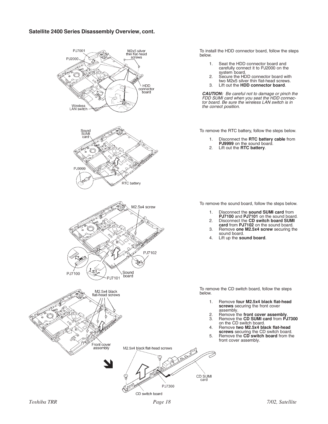
To install the HDD connector board, follow the steps below.
1. Seat the HDD connector board and carefully connect it to PJ2000 on the system board.
2. Secure the HDD connector board with two M2x5 silver thin
3. Lift out the HDD connector board.
CAUTION: Be careful not to damage or pinch the FDD SUMI card when you seat the HDD connec- tor board. Be sure the wireless LAN switch is in the correct position.
To remove the RTC battery, follow the steps below.
1. Disconnect the RTC battery cable from PJ9999 on the sound board.
2. Lift out the RTC battery.
To remove the sound board, follow the steps below.
1. Disconnect the sound SUMI card from PJ7100 and PJ7101 on the sound board.
2. Disconnect the CD switch board SUMI card from PJ7102 on the sound board.
3. Remove one M2.5x4 screw securing the sound board.
4. Lift up the sound board.
To remove the CD switch board, follow the steps below.
1. Remove four M2.5x4 black
2. Remove the front cover assembly.
3. Remove the CD SUMI card from PJ7300 on the CD switch board.
4. Remove two M2.5x4 black
5. Remove the CD switch board from the front cover assembly.
!
Toshiba TRR | Page 18 | 7/02, Satellite |