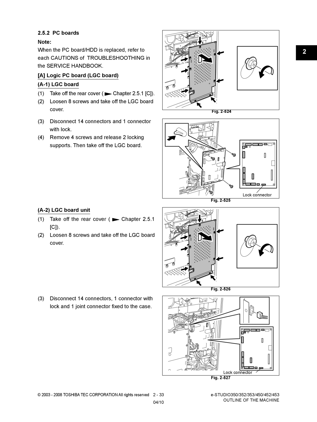
350, 353, 453, 452 specifications
The Toshiba 452, 282, and 352 models represent a significant leap in multifunction printing technology, designed for office environments that prioritize efficiency, reliability, and advanced features. These models are part of Toshiba's commitment to innovation and sustainability, emphasizing quality output while reducing environmental impact.One of the standout features of the Toshiba 452, 282, and 352 is their exceptional print quality. These multifunction printers utilize a high-resolution printing technology that ensures sharp text and vibrant images, making them suitable for a wide range of business applications, from standard documents to high-quality marketing materials. The printers are equipped with a versatile paper handling system, allowing users to accommodate various paper sizes and types, thereby enhancing their overall productivity.
In terms of speed, these models deliver impressive performance, with the capability to print up to 45 pages per minute for the 452, 28 pages per minute for the 282, and 35 pages per minute for the 352. This high-speed output is coupled with a fast first-page out time, ensuring that users spend less time waiting and more time focusing on their core business activities.
Moreover, the Toshiba 452, 282, and 352 are designed with user-friendly interfaces. Their intuitive touch-screen displays simplify navigation and operation, allowing users to quickly access frequently used functions. Customizable workflows and one-touch shortcuts further enhance usability, enabling employees to optimize their time in busy office settings.
Another crucial aspect of these models is their commitment to energy efficiency. Toshiba employs advanced technologies to ensure that the printers consume less power without compromising on performance. This not only helps businesses reduce their carbon footprint but also contributes to cost savings on energy bills.
Security is another critical feature integrated into the Toshiba 452, 282, and 352. With the increasing importance of data protection, these printers offer robust security measures, such as user authentication, secure printing, and data encryption. These features help safeguard sensitive information and ensure compliance with industry regulations.
Additionally, the multifunction capability of these printers allows them to serve as copiers, scanners, and fax machines, providing a comprehensive solution for office document management. Their ability to scan documents to email or to network folders enhances collaboration among team members.
In summary, the Toshiba 452, 282, and 352 models are versatile multifunction printers that offer a blend of speed, quality, and user-friendly features. Their commitment to sustainability and security makes them ideal choices for modern office environments looking to enhance productivity and efficiency.

