AR-B1375/AR-B1376 User s Guide

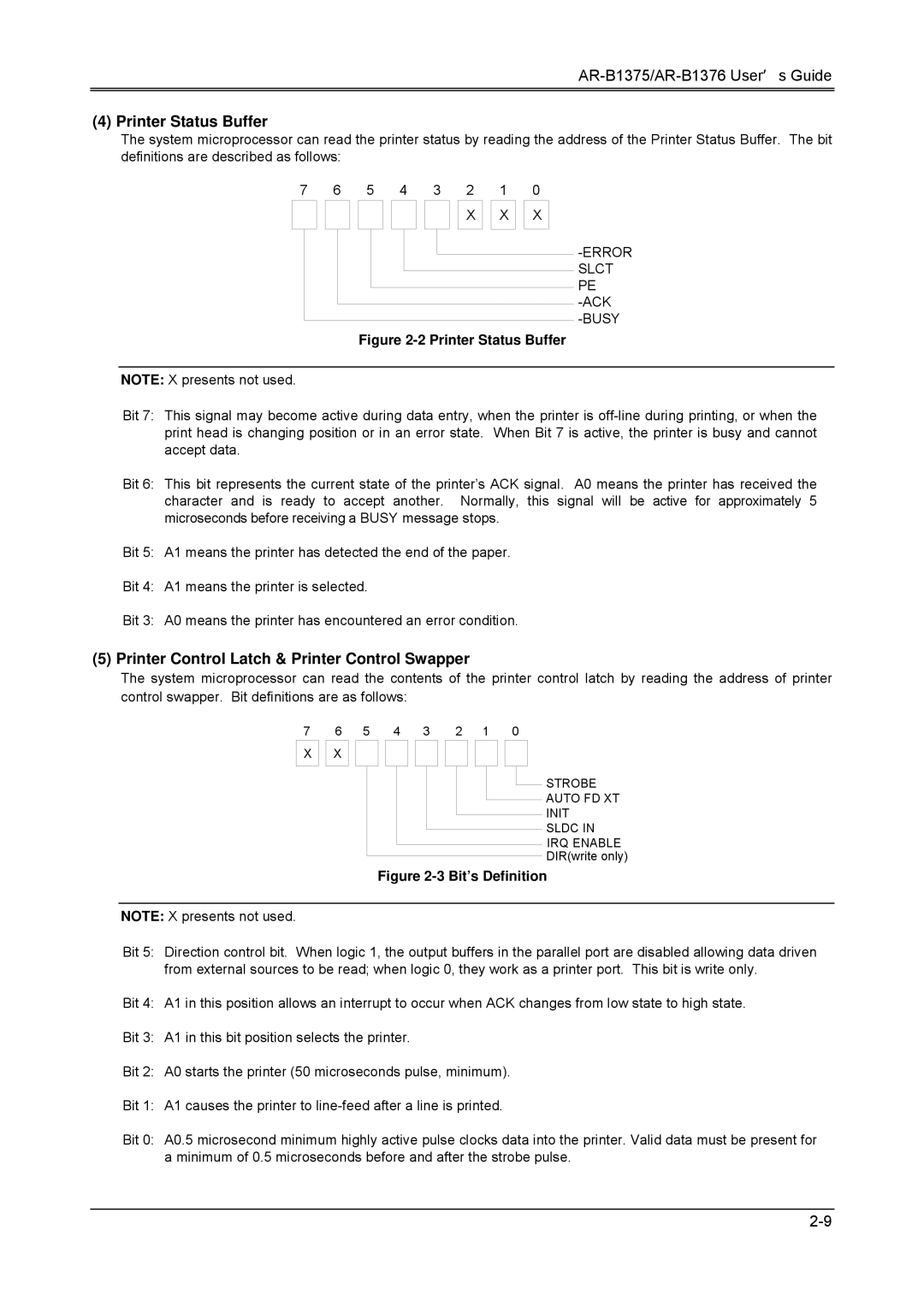
(4) Printer Status Buffer

The system microprocessor can read the printer status by reading the address of the Printer Status Buffer. The bit definitions are described as follows:

7


6

5

4

3

2


1


0


X


X


X


-ERROR SLCT PE -ACK -BUSY

Figure 2-2 Printer Status Buffer

NOTE: X presents not used.

Bit 7: This signal may become active during data entry, when the printer is off-line during printing, or when the print head is changing position or in an error state. When Bit 7 is active, the printer is busy and cannot accept data.

Bit 6: This bit represents the current state of the printer’s ACK signal. A0 means the printer has received the character and is ready to accept another. Normally, this signal will be active for approximately 5 microseconds before receiving a BUSY message stops.

Bit 5: A1 means the printer has detected the end of the paper.

Bit 4: A1 means the printer is selected.

Bit 3: A0 means the printer has encountered an error condition.

(5) Printer Control Latch & Printer Control Swapper

The system microprocessor can read the contents of the printer control latch by reading the address of printer control swapper. Bit definitions are as follows:

7


6

5

4

3

2


1


0


X


X


STROBE


AUTO FD XT


INIT


SLDC IN


IRQ ENABLE


DIR(write only)


Figure 2-3 Bit’s Definition

NOTE: X presents not used.

Bit 5: Direction control bit. When logic 1, the output buffers in the parallel port are disabled allowing data driven from external sources to be read; when logic 0, they work as a printer port. This bit is write only.

Bit 4: A1 in this position allows an interrupt to occur when ACK changes from low state to high state.

Bit 3: A1 in this bit position selects the printer.

Bit 2: A0 starts the printer (50 microseconds pulse, minimum).

Bit 1: A1 causes the printer to line-feed after a line is printed.

Bit 0: A0.5 microsecond minimum highly active pulse clocks data into the printer. Valid data must be present for a minimum of 0.5 microseconds before and after the strobe pulse.

2-9

Page 17
Image 17
Toshiba 386SX, AR-B1376 Printer Status Buffer, Printer Control Latch & Printer Control Swapper, Error Slct PE -ACK -BUSY

386SX, AR-B1376, AR-B1375 specifications

The Toshiba AR-B1375 and AR-B1376 are notable embedded computing solutions that incorporate the 386SX microprocessor architecture. Designed for various applications, these models focus on reliability, performance, and versatility, making them appealing choices for system integrators and developers.

At the core of the AR-B1375 and AR-B1376 is the Intel 386SX microprocessor. This landmark processor marked a significant advancement in computing technology, introducing a 32-bit architecture while maintaining compatibility with 16-bit applications. The 386SX is known for its efficient processing capabilities, offering both multitasking support and enhanced memory management. It operates at clock speeds ranging typically from 16 MHz to 25 MHz, contributing to its effectiveness in running industrial applications.

One of the key features of the AR-B1375 and AR-B1376 systems is their modular architecture, which allows for easy customization and expansion. This modularity means users can tailor the hardware according to specific requirements, making it suitable for a wide range of applications such as automation, telecommunications, and embedded systems.

Both models support various I/O options, ensuring seamless integration with peripherals and external devices. They typically come equipped with serial and parallel ports, as well as support for modern interfaces like USB. The systems also feature onboard expansion slots, enabling the addition of further functionality, such as additional memory or specialized processing units.

In terms of memory, the AR-B1375 and AR-B1376 support a range of RAM configurations, allowing users to scale their systems based on the application demands. The inclusion of EPROM and EEPROM options also facilitates easy updates and programmability, which is crucial for embedded systems that often require firmware adjustments over time.

Moreover, these models are known for their robust thermal management features, which are essential in industrial environments where conditions can be harsh. This capability ensures stable performance and longevity, reducing the risk of system failures due to overheating or environmental factors.

To summarize, the Toshiba AR-B1375 and AR-B1376, coupled with the 386SX microprocessor, offer a blend of performance, flexibility, and reliability. Their modular design, extensive I/O support, and memory scalability make them ideal for a variety of embedded computing applications, placing them as commendable options in the world of industrial computing solutions. These systems not only exemplify Toshiba's commitment to innovation but also contribute significantly to the functionality of embedded technologies in a rapidly evolving industry.