(8)Gamma correction
(9)Masking correction
(10)White balance
-OPWB (One Push White Balance) Effective range
Effective area
-MWB (Manual White Balance) Setting range
Setting method
(11)
(12)Power supply
(13)Power consumption
[Internal sync signal specification]
(1) Base clock frequency
[Trigger signal specification]
(1)External trigger input
-Input level
-Polarity
-Pulse width
-Input impedance
(2)Software trigger
[Output signal specification]
(1)BUSY_OUT
-Output level
-Polarity
(2)EXPOSE_OUT
-Output level
-Polarity
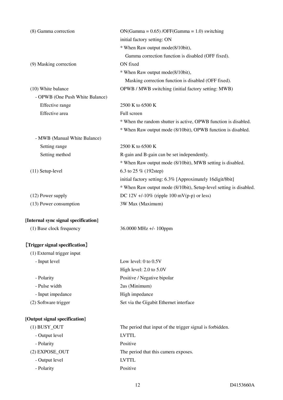
ON(Gamma = 0.65) /OFF(Gamma = 1.0) switching initial factory setting: ON
* When Raw output mode(8/10bit),
Gamma correction function is disabled (OFF fixed). ON fixed
* When Raw output mode(8/10bit),
Masking correction function is disabled (OFF fixed). OPWB / MWB switching (initial factory setting: MWB)
2500 K to 6500 K Full screen
*When the random shutter is active, OPWB function is disabled.
*When Raw output mode (8/10bit), OPWB function is disabled.
2500 K to 6500 K
*When Raw output mode (8/10bit), MWB setting is disabled. 6.3 to 25 % (192step)
initial factory setting: 6.3% [Approximately 16digit/8bit]
*When Raw output mode (8/10bit),
3W Max (Maximum)
36.0000 MHz +/- 100ppm
Low level: 0 to 0.5V
High level: 2.0 to 5.0V Positive / Negative bipolar 2us (Minimum)
High impedance
Set via the Gigabit Ethernet interface
The period that input of the trigger signal is forbidden.
LVTTL
Positive
The period that this camera exposes.
LVTTL
Positive
12 | D4153660A |
