GD-1210/1250/1270/1160/1260
Trademarks
Transportation/Installation
General Precautions at Service
When the option has been installed
Vorsicht
Page
Contents
Installation
Explanation to the Users
FAX Options
Models FAX unit 2nd line for FAX unit
Original size
Specifications
Folio
Embedded
DBm to -8 dBm The setting can be changed by 1 dB
Transmission system
DBm to 0 dBm Level -55 dBm or lower cannot be detected
ST-R
Paper size Dimension width x length Printing area
Comp
Features
11/04
Accessory GD-1210 GD-1250 GD-1270
Accessories and Parts
Following accessories and parts come with the FAX unit
Parts GD-1210 GD-1250 GD-1270
Extends the FAX functions when the FAX unit is installed
Options
Option Function STUDIO206L/256/306/356
Ments to be output
System List
STUDIO2500c/3500c/3510c
STUDIO2330C/2820C/2830C/3520C/3530C/4520C
NA/AU/EU/C/TW
STUDIO5520C/6520C/6530C
STUDIO205L/255/305/355/455
Offset Tray MJ-5005
STUDIO555/655/755/855
NA/EU-N/AU/C
STUDIO2040C/2540C/3040C/3540C/4540C
Pedestal PFP Feeder LCF KD-1027/C KD-1028 A4/LT/C
STUDIO5540C/6540C/6550C
STUDIO556/656/756/856
Saddle stitch Finisher MJ-1106/C
STUDIO206L/256/306/356/456
Inner Finisher MJ-1032 Saddle stitch MJ-1033
Overview
LINE2 connector Line connector TEL connector
Reversing automatic document feeder
TEL connector
Line connector
Drawers
STUDIO5520C/6520C/6530C, e-STUDIO5540C/6540C/6550C
Power switch TEL connector Line connector LINE2 connector
STUDIO205L/255/305/355/455, e-STUDIO206L/256/306/356/456
Power switch LINE2 connector Line connector TEL connector
STUDIO555/655/755/855, e-STUDIO556/656/756/856
FAX FAX PWR
Symbol Name Function
Layout of PC Boards
NCU MDM FAX FAX PWR
Recording Mode
LSU-RELATED Functions
Recording paper selection algorithm
Recording Paper Selection Algorithm and Printing Algorithm
Printing algorithm
ST against A3/B4/A4/LD/LT size originals respectively
Discard function Length of B Discard parameter Set value
Effective printing length
OFF
B4, A3 A4, B4 B5, B4 A5, A4
A5 , Comp LT, Comp COMP, LD LG/LT, LD ST, Folio B5, Folio
Setting for the split recording
Recording Paper and Function
Others
Table of the recording paper selection modes
Priority
Receiving FAX document, or by
Energy Saver Mode
User Functions
Energy Saver
Memory Reception
YES
Circuit Connection and Procedure to Change Mode
Dial call-up transmission to a telephone circuit
Standby state
Communication mode Toshiba original procedure
Selection of the communication mode
Procedure to select the transmission mode
Telephone circuit
This signal can be sent manually Signal form
Signaling System Diagram and Signal Forms
Circuit control signals
Signal name Signal form
Communication with the binary signals
Mode change possible Informing that there is the next
Image signal
Mode change is possible only for the original set manually
Receiver
Only error frame retransmitted 1 completed 2 completed
Frames received Error occurred
CFR
JOB Status button Cancel button
CED Nsfcsidis
MCF
Binary signals
PRI-EOM
PIP
PIN
PRI-MPS
FCF FIF FCS
When this frame is the last frame, X =
Format
FCF format of each binary signal
Binary signal Format
4800 bps, 2400 bps
9600 bps, 7200 bps
TCF
3 V.8/V.34 communication sequence
Standard procedure Transmitter Receiver
Line closed
Signal name Abbreviation Function Remarks
150 Hz
Tone signal between
Hz and 3,750 Hz in units
Data transmission
TRN
ALT
Receives an NSF sent from
Flag
Maintains the synchroniza 7E H Tion
Transmitter
Is completed
Image data Image data are sent. Transmitter
Scrambled data frame to be
Encoded image data Turn off Scrambled 1 is sent for
Transmission of one Is completed Flag
Short training Signal
PPS-EOP
Informs to disconnect the line
Line closed DIS cannot be recognized
Transmitter Receiver
Transmitter Receiver
DIALING/COMMUNICATION Control
DIALING/COMMUNICATION Control
FAX mode
FAX Automatic Switching
TEL mode
General functions
Configuration
GD-1210 GD-1160
GD-1250 / GD-1270 GD-1260
Configuration
Description of Circuits
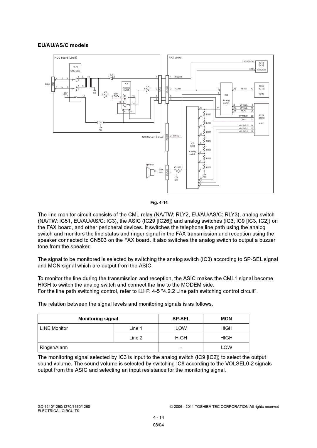
EU/AU/AS/C models
CML1
Line path switching control circuit
Signal Name Type Active Description Destination
ATT3DB1
IC3
RLY3, IC3
IC5
Line 1 Dial Pulse Generation Signal Q53
Dial pulse generation circuit
Line 1 Dial Pulse Generation Signal
Line current detection circuit
Line Current Detection Signal IC29 IC26
Line Reverse Current Detection Signal IC29 IC26
REVA1
Line 1 Current Detection Signal IC29 IC26
Current Reverse Line 1 Current Detection IC29 IC26 Signal
Line 1 CI Detect Signal IC29 IC26
CI detection circuit
Line 1 CI Detection Signal IC29 IC26
Line monitor circuit
NCU board Line1
Line Monitor
Monitoring signal
Ringer/Alarm
LOW High
Relation between the signals and sound volume is as follows
Sound volume
PC Boards
PWA-F-FAX-631 GD-1210
PWA-F-FAX-670 GD-1250/1270
08/04
08/04
PWA-F-MDM-563 GD-1160 PWA-F-MDM-671 GD-1260
PWA-F-FAX-POWER-631 GD-1210
Electrical Circuits
Installation
Explanation to the Users
Installation