4.CONNECTION
4.1 Standard Connection
Lans |
|
|
| Camera control unit | Cable |
|
|
|
|
| ||||
(option) |
|
| Camera cable |
|
|
|
|
|
|
| ||||
|
|
|
|
| for |
| (option) |
|
|
|
|
| ||
|
|
|
|
|
|
|
|
| ||||||
|
|
|
|
|
|
|
|
|
|
|
| |||
|
|
|
|
| (option) |
|
|
|
|
|
|
|
| |
|
|
|
|
|
|
|
|
|
|
|
|
| ||
|
|
|
|
|
|
|
|
|
|
|
|
|
| |
|
|
|
|
|
|
|
|
|
|
| ||||
|
|
|
|
|
|
|
|
| Frame grabber board, |
| Monitor | |||
|
|
|
|
|
|
|
| |||||||
|
|
|
|
|
| |||||||||
|
|
| (option) |
|
|
|
| image process |
|
|
| |||
|
|
|
|
|
|
| DC IN 12V | equipment etc. |
|
|
| |||
|
|
|
|
|
|
|
|
|
|
|
|
| ||
DC power supply (option)
When connection the frame grabber board, image process equipment, etc with power supply function, refer to the item “4.2 Caution on Connection”.
4. 2 Cautions on Connection
•Only use optional camera head model #
The use of another head may cause damage to the control unit and camera head.
•When connecting the camera cables, be sure to turn off the camera control unit and any other equipment connected to it.
•For DC power supply connecting to DC IN 12V terminal, use UL listed and/or CSA approved ungrounded type AC adaptor with the specifications described below.
Power supply voltage | : 12V DC±10% |
|
Current rating | : More than 830mA |
|
Ripple voltage | : Less than | |
• To connect DC IN 12V terminal, use the following connector listed below. | ||
Connector | : | |
| Pins 1, 2 : 12V , | Pins 3, 4 : GND |
•If the securing screw on the connector of the camera cable loosens, noise may appear on the screen. Be sure to tighten the connector completely.
•Use the standard cable for Camera Link.
•Input DC power (12V) either DC IN 12V terminal or DIGITAL terminal. If DC power is supplied input from both terminals, it may cause trouble.
•More than 830mA is necessary for proper functioning of the unit. Use power line with sufficient quan- tities of current rating. The unit dose not support PoCL standard.
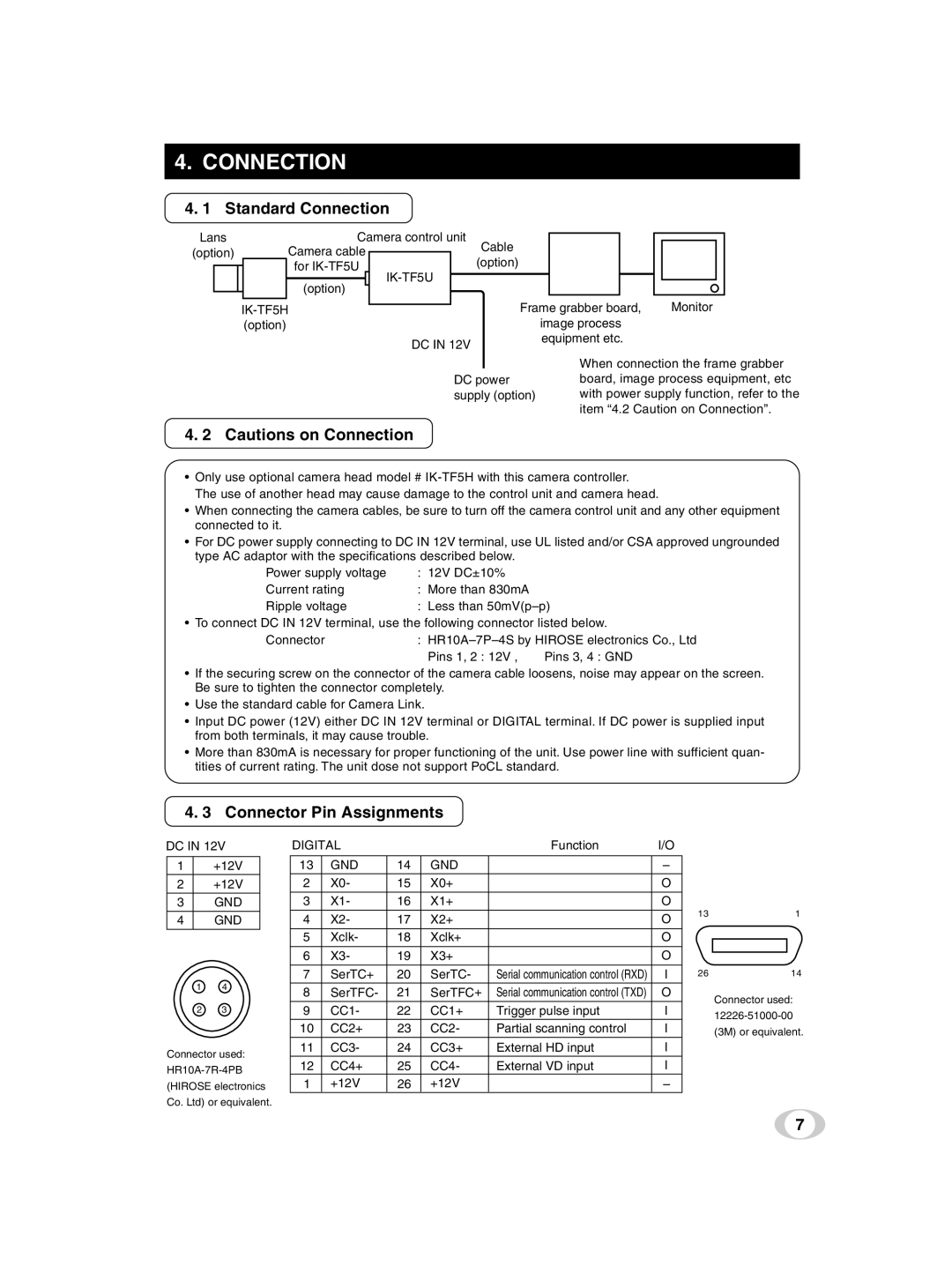
4. 3 Connector Pin Assignments
DC IN 12V
1+12V
2+12V
3GND
4GND
14
23
Connector used:
(HIROSE electronics
Co. Ltd) or equivalent.
DIGITAL |
|
| Function | I/O | |
13 | GND | 14 | GND |
| – |
2 | X0- | 15 | X0+ |
| O |
3 | X1- | 16 | X1+ |
| O |
|
|
|
|
|
|
4 | X2- | 17 | X2+ |
| O |
5 | Xclk- | 18 | Xclk+ |
| O |
|
|
|
|
|
|
6 | X3- | 19 | X3+ |
| O |
|
|
|
|
|
|
7 | SerTC+ | 20 | SerTC- | Serial communication control (RXD) | I |
8 | SerTFC- | 21 | SerTFC+ | Serial communication control (TXD) | O |
9 | CC1- | 22 | CC1+ | Trigger pulse input | I |
10 | CC2+ | 23 | CC2- | Partial scanning control | I |
11 | CC3- | 24 | CC3+ | External HD input | I |
12 | CC4+ | 25 | CC4- | External VD input | I |
1 | +12V | 26 | +12V |
| – |
131
2614
Connector used:
(3M) or equivalent.
7