Manuals
/
Brands
/
Computer Equipment
/
Laptop
/
Toshiba
/
Computer Equipment
/
Laptop
Toshiba
Satellite M40X
- page 100
1
100
219
219
Download
219 pages, 11.02 Mb
3. Test
s
and Diagnostic
s
3.17 LAN Test
3
-
26
[CONFIDENTIAL]
Satellite M40X/M45X/Satellite Pro M4
0X/EQUIUM M40X
Series Maintenance
Manual
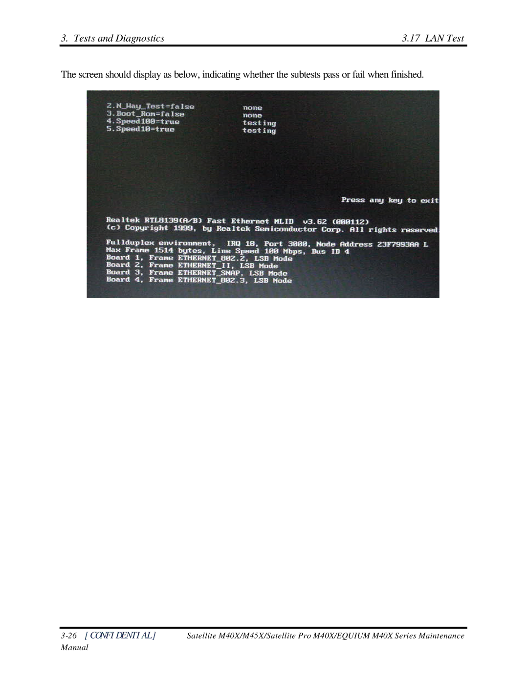
The screen should display as below, indicating whether the subtests pass or fail when finished.
Contents
Main
Toshiba Personal Computer Satellite M40X Maintenance Manual
TOSHIBA CORPORATION
Page
Preface
Page
Page
Page
Table of Contents
Page
Page
Page
Page
Page
Chapter 1 Contents
Page
1.1 Features
Page
Page
Page
1.2 System Unit
Page
1.3 2.5-inch Hard Disk Drive
1.4 Optical device Drives
Page
Page
1.5 Power Supply
Page
1.6 Batteries
Page
Page
Chapter 2 Troubleshooting Procedures
Page
Chapter 2 Contents
Page
2.1 Troubleshooting Introduction
2.2 Troubleshooting Flowchart
2.3 Power Supply Troubleshooting 2 Troubleshooting Procedures
A
Figure 2-1 Troubleshooting flowchart (1/2)
2 Troubleshooting Procedures 2.3 Power Supply Troubleshooting
A
Figure 2-1 Troubleshooting flowchart (2/2)
Page
Page
2.3 Power Supply Troubleshooting 2 Troubleshooting Procedures
2.3 Power Supply Troubleshooting
Figure 2-2 Power Supply Troubleshooting Process
END
Page
Page
AC adaptor System
board Battery
AC adaptor cord AC power cord
Page
2 Troubleshooting Procedures 2.4 Display Troubleshooting
2.4 Display Troubleshooting
Figure 2-3 Display troubleshooting process
Page
Page
2.5 Keyboard Troubleshooting 2 Troubleshooting Procedures
2.5 Keyboard Troubleshooting
Figure 2-4 Keyboard troubleshooting process
Page
2.6 External USB Devices Troubleshooting 2 Troubleshooting Procedures
2.6 External USB Devices Troubleshooting
Figure 2-5 External USB device troubleshooting process
Page
2.7 TV-Out Failure Troubleshooting 2 Troubleshooting Procedures
2.7 TV-Out Failure Troubleshooting
Figure 2-6 TV-out troubleshooting process
Page
2.8 Printer Port Troubleshooting 2 Troubleshooting Procedures
2.8 Printer Port Troubleshooting
Figure 2-7 Printer port troubleshooting process
Page
2.9 TouchPad Troubleshooting
Page
2.10 Speaker Troubleshooting 2 Troubleshooting Procedures
2.10 Speaker Troubleshooting
Figure 2-9 Speaker troubleshooting process
Page
2.11 Optical Drive Troubleshooting 2 Troubleshooting Procedures
2.11 Optical Drive Troubleshooting
Figure 2-10 Optical drive troubleshooting process
Page
Page
2 Troubleshooting Procedures 2.12 Modem Troubleshooting
2.12 Modem Troubleshooting
Figure 2-11 Modem troubleshooting process
Page
2 Troubleshooting Procedures 2.13 PCMCIA Troubleshooting
2.13 PCMCIA Troubleshooting
Figure 2-12 PCMCIA troubleshooting process
Page
2 Troubleshooting Procedures 2.14 IEEE 1394 Troubleshooting
2.14 IEEE 1394 Troubleshooting
Figure 2-13 IEEE 1394 troubleshooting process
Page
2 Troubleshooting Procedures 2.15 Wireless LAN Troubleshooting
2.15 Wireless LAN Troubleshooting
Figure 2-14 Wireless LAN troubleshooting process
Page
Page
Page
Contents
Page
3.1 The Diagnostic Test
3.2 Executing the Diagnostic Test
Page
Page
Page
3.3 Config Check Test
3.4 DMI Check Test
3.5 PIO Loopback Test
Page
3.6 Speaker Audio Test
3.7 Fan ON/OFF Test
3.8 Main Battery Charge Test
3.9 FDD Test
Page
3.10 CD-ROM Test
3.11 Keyboard Test
Page
Page
3.12 Mouse (Pad) Test
Page
3.13 LCD Pixels Mode Test
3.14 Lid Switch Test
3.15 HDD R/W Test
Page
3.16 LAN Test
Page
3.17 RTC Test
Page
Page
Page
Chapter 4 Contents
Page
Page
4.1 General
Page
Page
Page
Page
Page
4.2 Battery
Page
4.3 PC Card
Page
4.4 HDD
Page
4.5 Optical Drive Module
Page
4.6 Optical Drive
Page
4.7 Keyboard
Page
Page
4.8 Wireless LAN Unit
Page
4.9 Expansion Memory
Page
Page
4.10 Modem
Page
4.11 Display Assembly
Page
Page
4.12 Top Cover
Page
Page
4.13 Touch Pad
Page
4.14 Speakers
4.15 System Board
Page
4.16 Fan & CPU
Page
Page
4.17 Display Mask
Page
4.18 LCD Module
Page
Page
4.19 FL Inverter Board
Page
Page
Appendix Contents
Page
Page
Appendix A Handling the LCD Module
Precautions for handling the LCD module
Page
Page
Page
Page
Page
Appendix B Board Layout
B.1 System Board (FRDSY*) Bottom View
Page
Page
Page
Page
Appendix C Pin Assignments
System Board C.1 JP25
Table C-1 SODIMM I/F pin assignments (200-PIN) (1/4)
Table C-1 SODIMM I/F pin assignments (200-PIN) (2/4)
Table C-1 SODIMM I/F pin assignments (200-PIN) (3/4)
Table C-1 SODIMM I/F pin assignments (200-PIN) (4/4)
C.2 JP1
C.3 JP8
Table C-4 HDD I/F pin assignments (44-pin)
C.4 JP13
Table C-5 ODD I/F pin assignments (52-pin)
C.5 JP2
Table C-6 Parallel I/F pin assignments (25-pin)
C.6 JP12
Table C-7 PC Card I/F pin assignments (84-pin) (1/2)
Table C-7 PC Card I/F pin assignments (84-pin) (2/2)
C.7 JP11
Table C-8 Mini PCI I/F pin assignments (124-pin) (1/2)
Table C-8 Mini PCI I/F pin assignments (124-pin)(2/2)
C.8 JP6
Page
C.10 JP7
Table C-9-1 JP7 Fan I/F pin assignments (3-pin)
C.11 PJP1
Table C-10 AC Adaptor Connector pin assignments (6-pin)
C.14 JP5
Table C-13 Double USB Connector pin assignments (12-pin)
C.15 JP23
Table C-14 Single USB Connector pin assignments (4-pin)
C.16 JP16
C.17 JP17
Table C-16 SW/LED Connector pin assignments (14-pin)
C.18 JP16
Table C-17 T/P Connector pin assignments (12-pin)
C.19 JP19
Table C-18 KB Connector pin assignments (38-pin)
C.20 JP20
Table C-19 1394 Connector pin assignments (4-pin)
C.21 JP21
Table C-20 SPK Connector pin assignments (4-pin)
C.22 JP22
Page
Appendix D Keyboard Scan/Character Codes
Table D-1 Scan codes (set 1 and set 2) (1/4)
Table D-1 Scan codes (set 1 and set 2) (2/4)
Table D-1 Scan codes (set 1 and set 2) (3/4)
Page
Satellite M40X Series Maintenance Manual [CONFIDENTIAL] D-5
Table D-2 Scan codes with left Shift key
D-6 [CONFIDENTIAL] Satellite M40X Series Maintenance Manual
Table D-3 Scan codes in Numlock mode
Table D-4 Scan codes with Fn key
Code set 1 Code set 2 Cap No.
Table D-5 Scan codes in overlay mode
Table D-6 No.124 key scan code
Page
Appendix E
Key Layout
Page
Page
Page
Page
Page
Page
Page
Page
Page
Page
Page
Page
Page
Page
Appendix F Series Screw Torque List
Table F-1 Series Screw Torque List
Page
Page
Page
Page
Appendix G Reliability