(2) Operating (Write) | no error | ||
| 14.7 m/s2 [1.5 G] | (Horizontal) | |
| 7.8 m/s2 [0.8 G] | (Vertical) | |
| (Half sine wave 11 ms/10 s interval) | ||
(3) | no damage | ||
| 490 m/s2 [50 G] | (Half sine wave 11 ms) | |
| 980 m/s2 [100 G] | (Half sine wave 3 ms) | |
(4) Drop (Packaged) | no damage |
| |
(a) Bulk Package (50 pcs) | 1 drop at 0.4 m (Bottom side only) | ||
(b) Bulk Package (20 pcs) | 0.6 m drops once for each | ||
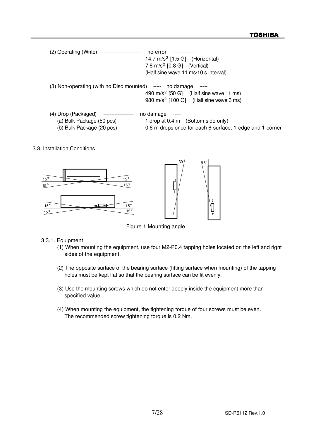
3.3. Installation Conditions
15°
15°
15°
15°
15°
15°
15°
15 °
30 ° | 15 ° |
|
|
|
|
|
|
|
|
|
| ||
|
|
|
|
|
|
|
|
|
|
|
|
|
|
|
|
|
|
|
|
|
|
|
|
|
|
|
|
|
|
|
|
|
|
|
|
|
|
|
|
|
|
|
|
|
|
|
|
|
Figure 1 Mounting angle
3.3.1.Equipment
(1)When mounting the equipment, use four M2-P0.4 tapping holes located on the left and right sides of the equipment.
(2)The opposite surface of the bearing surface (fitting surface when mounting) of the tapping holes must be kept flat so that the bearing surface can be fit evenly.
(3)Use the mounting screws which do not enter deeply inside the equipment more than specified value.
(4)When mounting the equipment, the tightening torque of four screws must be even.
The recommended screw tightening torque is 0.2 Nm.
7/28 |
|
