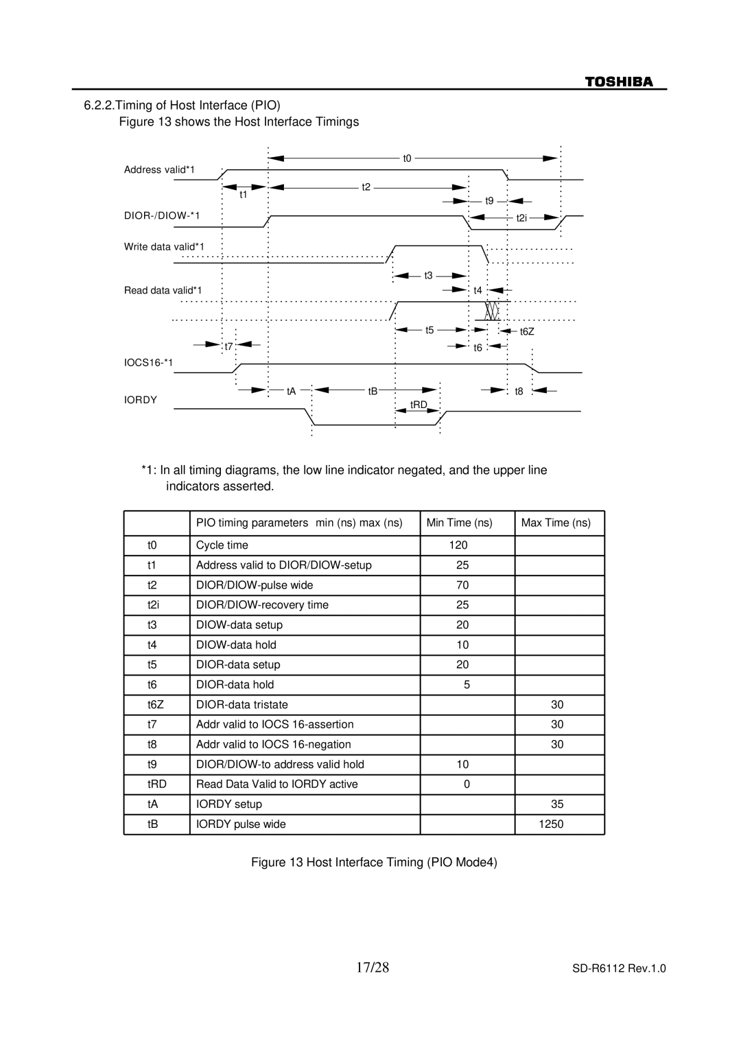
6.2.2.Timing of Host Interface (PIO)
Figure 13 shows the Host Interface Timings
Address valid*1
![]()
![]()
![]()
![]() t2 t1
t2 t1
Write data valid*1
Read data valid*1
![]() t7
t7 ![]()
![]()
![]()
![]() tA
tA ![]()
![]()
![]() tB
tB
IORDY
t0
![]()
![]() t9
t9
t2i
![]()
![]() t3
t3 ![]()
t4
t5 |
|
|
|
|
| t6Z |
|
|
| ||||
|
t6
![]()
![]() t8 tRD
t8 tRD
*1: In all timing diagrams, the low line indicator negated, and the upper line indicators asserted.
| PIO timing parameters min (ns) max (ns) | Min Time (ns) | Max Time (ns) |
|
|
|
|
t0 | Cycle time | 120 |
|
|
|
|
|
t1 | Address valid to | 25 |
|
|
|
|
|
t2 | 70 |
| |
|
|
|
|
t2i | 25 |
| |
|
|
|
|
t3 | 20 |
| |
|
|
|
|
t4 | 10 |
| |
|
|
|
|
t5 | 20 |
| |
|
|
|
|
t6 | 5 |
| |
|
|
|
|
t6Z |
| 30 | |
|
|
|
|
t7 | Addr valid to IOCS |
| 30 |
|
|
|
|
t8 | Addr valid to IOCS |
| 30 |
|
|
|
|
t9 | 10 |
| |
|
|
|
|
tRD | Read Data Valid to IORDY active | 0 |
|
|
|
|
|
tA | IORDY setup |
| 35 |
|
|
|
|
tB | IORDY pulse wide |
| 1250 |
|
|
|
|
Figure 13 Host Interface Timing (PIO Mode4)
17/28 |
|
