5.Functions
5.1.Disc Data Configurations
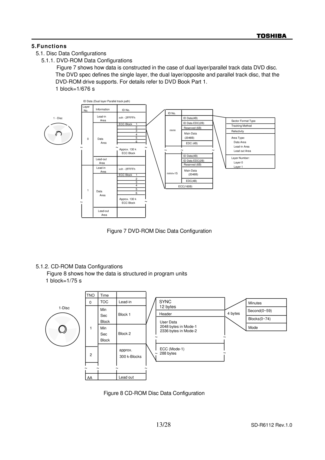
5.1.1.DVD-ROM Data Configurations
Figure 7 shows how data is constructed in the case of dual layer/parallel track data DVD disc. The DVD spec defines the single layer, the dual layer/opposite and parallel track disc, that the DVD-ROM drive supports. For details refer to DVD Book Part 1.
1 block=1/676 s
ID Data (Dual layer Parallel track path)
| Layer | Information |
|
| No. | ID No. | |
1 - Disc |
| xxh - 2FFFFh | |
| Area | ||
|
|
| |
|
|
| ECC Block 1 |
|
|
| 2 |
|
|
| 3 |
|
|
| 4 |
| 0 | Data | 5 |
| 6 | ||
|
| Area | |
|
|
|
~~ Approx. 130 k ECC Block
|
|
|
| |
|
|
| Area |
|
|
|
| xxh - 2FFFFh | |
|
|
| Area | |
|
|
|
| |
|
|
|
| ECC Block 1 |
|
|
|
| 2 |
|
|
|
| 3 |
|
|
|
| 4 |
|
| 1 | Data | 5 |
|
| 6 | ||
|
|
| ||
|
|
| Area | |
|
|
|
| |
~ |
|
| Approx. 130 k | |
|
| ECC Block | ||
|
|
|
| |
|
|
| Area |
|
|
|
|
|
|
|
|
|
|
|
|
|
|
|
|
| ID No. |
|
|
|
|
|
|
|
|
| ID Data(4B) |
|
|
|
|
|
|
| ID Data EDC(2B) |
|
|
|
|
| nnnn |
| Reserved (6B) |
|
|
|
|
|
| Main Data |
|
| |
|
|
|
|
|
|
| |
|
|
|
|
| (2048B) |
|
|
|
|
|
|
|
|
|
|
|
|
|
|
| EDC (4B) |
|
|
~ |
|
|
|
|
|
| |
~ | ~ | ~ | |||||
|
|
|
|
| |||
|
|
|
|
|
|
|
|
|
|
|
|
| ID Data(4B) |
|
|
|
|
|
|
| ID Data EDC(2B) |
|
|
|
|
|
|
| Reserved (6B) |
|
|
|
|
| nnnn+15 |
| Main Data |
|
|
|
|
|
| (2048B) |
|
| |
|
|
|
|
|
|
| |
|
|
|
|
|
|
|
|
|
|
|
|
| EDC(4B) |
|
|
|
|
|
| ECC(160B) |
|
| |
|
|
|
|
|
|
|
|
~ |
|
|
|
|
|
| |
Sector Format Type
Tracking Method
Refectivity
Area Type: Data Area
Layer Number:
Layer 0
Layer 1
Figure 7 DVD-ROM Disc Data Configuration
5.1.2. CD-ROM Data Configurations
Figure 8 shows how the data is structured in program units 1 block=1/75 s
TNO | Time |
|
0 | TOC | |
|
|
|
| Min |
|
| Sec | Block 1 |
|
| |
| Block |
|
1 | Min |
|
| Sec | Block 2 |
| Block |
|
|
|
|
|
| approx. |
|
| |
2 |
| 300 |
|
| |
|
|
|
|
|
|
SYNC 12 bytes
Header
User Data
2048 bytes in
2336 bytes in
~
ECC
~288 bytes
4 bytes
~
~
Minutes
Second(0~59)
Blocks(0~74)
Mode
~ | ~ | ~ | ~ | ||||
|
|
|
|
|
|
|
|
| AA |
|
|
|
| Lead out |
|
Figure 8 CD-ROM Disc Data Configuration
13/28 |
|