General Information

OA/RA Actuator (Option)

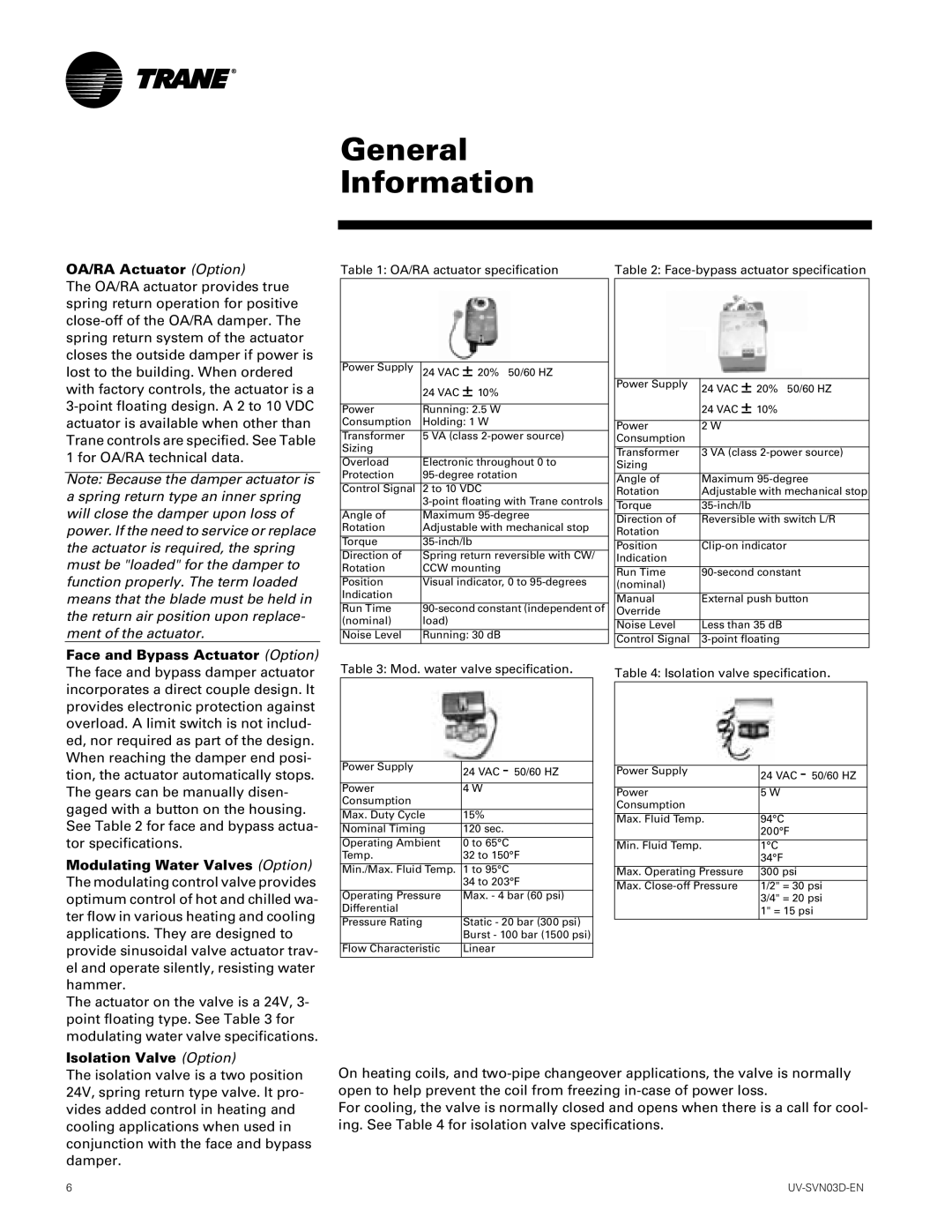
The OA/RA actuator provides true spring return operation for positive close-off of the OA/RA damper. The spring return system of the actuator closes the outside damper if power is lost to the building. When ordered with factory controls, the actuator is a 3-point floating design. A 2 to 10 VDC actuator is available when other than Trane controls are specified. See Table 1 for OA/RA technical data.

Note: Because the damper actuator is a spring return type an inner spring will close the damper upon loss of power. If the need to service or replace the actuator is required, the spring must be "loaded" for the damper to function properly. The term loaded means that the blade must be held in the return air position upon replace- ment of the actuator.

Table 1: OA/RA actuator specification


Power Supply

24 VAC ± 20% 50/60 HZ


24 VAC ± 10%


Power

Running: 2.5 W

Consumption

Holding: 1 W


Transformer

5 VA (class 2-power source)

Sizing


Overload

Electronic throughout 0 to

Protection

95-degree rotation


Control Signal

2 to 10 VDC


3-point floating with Trane controls


Angle of

Maximum 95-degree

Rotation

Adjustable with mechanical stop

Torque

35-inch/lb

Direction of

Spring return reversible with CW/

Rotation

CCW mounting


Position

Visual indicator, 0 to 95-degrees

Indication


Run Time

90-second constant (independent of

(nominal)

load)

Noise Level

Running: 30 dB

Table 2: Face-bypass actuator specification


Power Supply

24 VAC ± 20% 50/60 HZ


24 VAC ± 10%


Power

2 W

Consumption


Transformer

3 VA (class 2-power source)

Sizing


Angle of

Maximum 95-degree

Rotation

Adjustable with mechanical stop


Torque

35-inch/lb

Direction of

Reversible with switch L/R

Rotation


Position

Clip-on indicator

Indication


Run Time

90-second constant

(nominal)


Manual

External push button

Override


Noise Level

Less than 35 dB

Control Signal

3-point floating

Face and Bypass Actuator (Option) The face and bypass damper actuator incorporates a direct couple design. It provides electronic protection against overload. A limit switch is not includ- ed, nor required as part of the design. When reaching the damper end posi- tion, the actuator automatically stops. The gears can be manually disen- gaged with a button on the housing. See Table 2 for face and bypass actua- tor specifications.

Modulating Water Valves (Option) The modulating control valve provides optimum control of hot and chilled wa- ter flow in various heating and cooling applications. They are designed to provide sinusoidal valve actuator trav- el and operate silently, resisting water hammer.

The actuator on the valve is a 24V, 3- point floating type. See Table 3 for modulating water valve specifications.

Isolation Valve (Option)

Table 3: Mod. water valve specification.


Power Supply

24 VAC - 50/60 HZ


Power

4 W

Consumption


Max. Duty Cycle

15%

Nominal Timing

120 sec.

Operating Ambient

0 to 65°C

Temp.

32 to 150°F


Min./Max. Fluid Temp.

1 to 95°C


34 to 203°F


Operating Pressure

Max. - 4 bar (60 psi)

Differential


Pressure Rating

Static - 20 bar (300 psi)


Burst - 100 bar (1500 psi)


Flow Characteristic

Linear

Table 4: Isolation valve specification.


Power Supply

24 VAC - 50/60 HZ


Power

5 W

Consumption


Max. Fluid Temp.

94°C


200°F


Min. Fluid Temp.

1°C


34°F

Max. Operating Pressure

300 psi

Max. Close-off Pressure

1/2" = 30 psi


3/4" = 20 psi


1" = 15 psi


The isolation valve is a two position 24V, spring return type valve. It pro- vides added control in heating and cooling applications when used in conjunction with the face and bypass damper.

On heating coils, and two-pipe changeover applications, the valve is normally open to help prevent the coil from freezing in-case of power loss.

For cooling, the valve is normally closed and opens when there is a call for cool- ing. See Table 4 for isolation valve specifications.

6

UV-SVN03D-EN

Page 6
Image 6
Trane 1500 CFM, 750 CFM manual OA/RA Actuator Option, Isolation Valve Option

750 CFM, 1500 CFM specifications

Trane has long been a leader in the heating, ventilation, and air conditioning (HVAC) industry, and among its extensive product range, the Trane 1500 CFM and 750 CFM air handling units stand out due to their innovative design and performance capabilities. These units are engineered to provide exceptional airflow and efficiency, catering to a variety of commercial and industrial environments.

One of the main features of the Trane 1500 CFM and 750 CFM units is their ability to maintain optimal indoor air quality. Both units feature high-efficiency air filters that effectively capture dust, allergens, and other airborne particles, ensuring that the air quality remains high. This is particularly important in commercial spaces, where the health and comfort of occupants is a top priority.

In terms of energy efficiency, the Trane units are equipped with advanced technologies that minimize energy consumption while maximizing cooling and heating performance. The units are designed to comply with the most stringent efficiency standards, making them an environmentally friendly choice. The use of variable speed fans allows for precise control over airflow, further enhancing energy savings by adjusting to the specific demands of the space.

Another notable characteristic of the Trane air handling units is their robust construction. Built with high-quality materials, they are designed to withstand harsh environmental conditions, ensuring durability and reliability over long periods of use. The units come with sound-attenuating features, making them suitable for noise-sensitive environments, while their compact design facilitates easy installation in limited spaces.

Trane also integrates smart technology into its air handling units, enabling connectivity with building management systems (BMS). This feature allows for real-time monitoring and remote control of unit operations, providing facility managers with valuable insights into performance and energy usage. Such connectivity not only improves operational efficiency but also simplifies maintenance tasks by providing timely alerts and diagnostics.

In summary, the Trane 1500 CFM and 750 CFM air handling units are designed with key features that enhance air quality, energy efficiency, and user convenience. Their innovative technologies and durable construction make them a reliable choice for various commercial applications, ensuring a comfortable and healthy indoor environment for all occupants. With Trane's commitment to quality and performance, these units represent the forefront of HVAC technology.