Installation
Soldering procedures are as follows:
1Remove actuator as stated earlier.
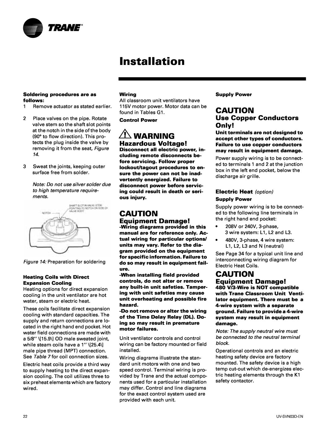
2Place valves on the pipe. Rotate valve stem so the shaft slot points at the notch in the side of the body (90° to flow direction). This pro- tects the plug inside the valve by removing it from the seat, Figure 14.
3Sweat the joints, keeping outer surface free from solder.
Note: Do not use silver solder due to high temperature require- ments.
Figure 14: Preparation for soldering
Heating Coils with Direct
Expansion Cooling
Heating options for direct expansion cooling in the unit ventilator are hot water, steam or electric heat.
These coils facilitate direct expansion cooling with standard capacities. The supply and return connections are lo- cated in the right hand end pocket. Hot water field connections are made with a 5/8’’ \[15.9\] OD male sweated joint, while steam coils have a 1’’ \[25.4\] male pipe thread (MPT) connection. See Table 7 for coil connection sizes.
Electric heat coils provide a third way to supply heating to the direct expan- sion cooling. The coil utilizes three to six preheat elements which are factory wired.
Wiring
All classroom unit ventilators have 115V motor power. Motor data can be found in Tables G1.
Control Power
! WARNING
Hazardous Voltage!
Disconnect all electric power, in- cluding remote disconnects be- fore servicing. Follow proper lockout/tagout procedures to en- sure the power can not be inad- vertently energized. Failure to disconnect power before servic- ing could result in death or seri- ous injury.
CAUTION
Equipment Damage!
Unit ventilator controls and control wiring can be factory mounted or field installed.
Wiring diagrams illustrate the stan- dard unit motors with one and two speed control. Terminal wiring is pro- vided by Trane and the actual compo- nents used for a particular installation may differ. Control and line diagrams for the exact control system used are provided with each unit.
Supply Power
CAUTION
Use Copper Conductors Only!
Unit terminals are not designed to accept other types of conductors. Failure to use copper conductors may result in equipment damage.
Power supply wiring is to be connect- ed to terminals 1 and 2 at the junction box in the left end pocket, below the discharge air grille.
Electric Heat (option)
Supply Power
Supply power wiring is to be connect- ed to the following line terminals in the right hand end pocket:
•208V or 240V,
3 wire system: L1, L2 and L3.
•480V,
See Page 34 for a typical unit line and interconnecting wiring diagram for Electric Heat Coils.
CAUTION
Equipment Damage!
480
Note: The supply neutral wire must be connected to the neutral terminal block.
Operational controls and an electric heating safety device are factory mounted. The safety device is a high temp
22 |