IntelliPak
Models BO and later Design Sequence
Special Note on Refrigeration Emissions
General Information
Psig = Pounds-per-square-inch, gauge pressure
Contents
Installation Information
General
Unit Nameplate
Model Number Description
Self-Contained Ship-With Accessory Model Number Description
After-Shipment Accessory Model Number
Pre-Installation Installation Considerations
Receiving Checklist
Receiving and Handling
Shipping Package
Installation Preparation
Service Access
Table I-PC-1. SCWG/SIWG/SCRG/SIRG Clearance Requirements
Rigging and Unit Handling
Figure I-PC-6. Split-apart unit gravity block location
Rigging and Handling
Unit Shipping
Split-Apart Unit Assembly
IntelliPak Units UCM Only
Remove panels FML, FMM, and FMR
Units withThermostat Only
Figure I-PC-9 How to assemble the split apart modular unit
Skid Removal
Pre-Installation Checklist
External Unit Isolation
Installation Dimensions Weights
SCWG/SIWG Unit Metric- mm
SCRG/SIRG Unit English inches
Installation Weights
SCRG/SIRG Unit Metric mm
Unit Dimensions Metric mm
Unit Dimensions English, inches
SCRG/SIRG/SCWG/SIWG Detail
Hot Water Coil Dimensions Metric mm
Hot Water Coil Dimensions English inches
Hot Water Coil
Steam Coil Dimensions Metric mm
Steam Coil Dimensions English inches
Steam Coil
Electric Heat Coil
Waterside Economizer
Airside Economizer Dimensions English inches
Airside Economizer Dimensions Metric mm
Dimensions Weights
Detail a Detail B
Variable Frequency Drive Dimensions Metric mm
Variable Frequency Drive Dimensions English inches
Variable Frequency Drive
Variable Frequency Drive with Bypass
Variable Frequency Drive With Bypass Dimensions Metric mm
Flexible Horizontal Discharge Plenum Dimensions Metric mm
Flexible Horizontal Discharge Plenum
Table I-DW-1. Unit Weights, English SCWG/SCRG/SIWG/SIRG
Metric SCWG//SIWG/SCRG/SIRG
Mechanical
Duct Connections
Condenser Connections
Water Piping
Table I-MR-1. Water Connection Sizes
General Waterside Recommendations Cooling Towers
Waterside Piping Arrangements
Refrigerant Piping Air-Cooled Units Only
Brazing Procedures
Leak Test Remote Air-cooled Units Only
Unit Wiring Diagrams
Supply Power Wiring
Control Power
Electrical
Selection Procedures
Pre-Startup
Pre-Startup Procedures
Supply Fan Isolators
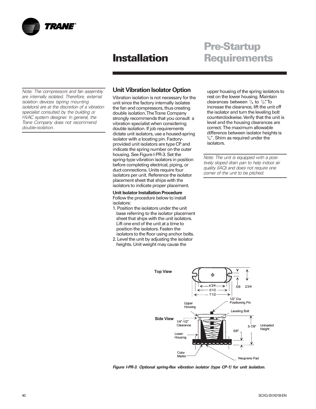
Unit Vibration Isolator Option
Figure I-PR-4. Correct plenum insulation placement
Waterside Economizer Installation Procedure
Figure I-PR-5. Installing the waterside economizer
Pre-Startup
Assembly
Hydronic Coil Installation
Installation Procedure
Electric Heat Installation
Electric Heat Coil Wiring Procedure
Table I-PR-5. Electric Heat Dimensions Metric mm
Table I-PR-3. Available Electric Heat kW
Variable Frequency Drive Option VFD
Airside Economizer Installation
Unit Installation
Field Wiring Connections
Unit Handling
Installing theTransducer
Transducer Location
Table I-PR-6. Control Wire Size and Maxi- mum Length
Wiring the Remote Air-cooled Ccrc
Remote Mounted Thermostat Option
Standard with All Units
CV Unit Zone Sensor Option
VAV Unit Zone Sensor Option
Remote Zone Sensor Options
CV and VAV Unit Zone Sensor Options
BAYSENS010 Description
BAYSENS014 Description
BAYSENS013 Description
Zone Sensor Installation
Table I-PR-7. Zone Sensor Maximum Lengths and Wire Size
Mounting Location
Mounting the Subbase
Figure I-PR-22. Zone sensor mounting hole locations
ConstantVolume Zone Sensor BAYSENS019 Description
Variable Air Volume Zone Sensor BAYSENS020B Description
Night setback sensor, Accessory Model
Programmable Night Setback Zone Sensors
Figure I-PR-26. BAYSENS019 dimensions
Airflows from adjacent zones or other units
Timeclock Installation
Timeclock Installation Checklist
Wiring theTimeclock
Time Clock Option
Installing the Remote Human Interface Panel
Human Interface HI Panel
Remote Human Interface Panel
HI Location Recommendations
Procedure
Wall Mounting the RHI Panel
Pre-Startup
Wiring the Remote Human Interface
Communication Link ShieldedTwisted Pair Wiring
Interprocessor Communication Bridge Module Wiring
Do not run communication link between buildings
Connecting to Tracer Summit
Pre-Startup Checklist
Programmable Zone Sensor Option
Heat supply air Cool supply air Warmup temperature
During Programming Indicates
Keypad Operation
Temporary Manual Override
Time Button
Keypad Lockout
Up and Down Button Arrows
Temporary Override Run Mode
Figure I-P-5. Override run mode screen
Table I-P-1. Zone Sensor BAYSENS019 Option Menu Settings
Option Menu and Keypad Operation
Using Intelligent Copy
Remote Panel Indicator Signals From UCM to ZSM
Intelligent Copy
Off Flashing
Icon Descriptions
BAYSENS019 Icon Descriptions
BAYSEN020 Icon Descriptions
Figure I-P-10.BAYSENS020 complete icon display
Setting theTime
Programming theTime Clock Option
Programming
To review and change programs
Adjust setpoints at the HI
Unit Startup Procedures
Unit Startup
Evaporator
Startup Log
Compressor Amp Draw
Water Cooled Units
Air Cooled Units
Owner General Information
Points List
Unit Control Components
General Owner Information
RTM Module Board Standard on all Units
Sensor Resistance vs. Temperature
Occupied/Unoccupied Contacts
Emergency Stop Input
VAV Box Option
Heat Module
Ventilation Override Module VOM Option
Purge sequence D
Application are switch 1 off, 2 on, and 3 off
Supply fan on Supply fan VFD on if equipped
Gbas Analog Inputs
Gbas Binary Outputs
Gbas Binary Input
If the setpoint range is between 50-90 F IPV = SP 50 0.1 +
Table O-GI-6. Gbas Analog Input Setpoints
Table O-GI-7. Gbas Input Voltage Corresponding Setpoints
Waterside Components
Variable Water Flow
Unit Airside Components
Can be enabled by the operator
Airside Economizer Option
Air-Cooled Condensers
Airside Economizer Interface with Comparative Enthalpy
Input Devices and System Functions
Return Air Temperature Sensor
Supply Air Temperature Sensor
Supply Airflow Proving Switches
Filter Switch
Control Sequences Operation
Sequence Owner Operation
Unoccupied
Timed Override Activation ICS
Occupied Sequence Operation
Supply Air Setpoint Reset VAV Units Only
Mechanical Cooling
Water-Cooled Units Only
Electric Heat
Compressors
Table O-SO-1. Compressor Stages
Table O-SO-2. Pressure Cutouts
Step Control
Table O-SO-3. IntelliPakUnit Cooling Capacity Percent
Service Valves
Evaporator Coil Frost Protection
Owner Maintenance
Maintenance Procedures
Inspecting and Cleaning the Drain Pan
Inspecting and Cleaning the Fan
Supply Fan
Fan Drive
Follow the procedure below to measure belt tension
Adjusting BeltTension
Fan Bearings
Fan Belt Tension
Figure O-M-5. Fan assembly
Refrigerant System
Nitrogen into the system to raise the pressure to 100 psig
Evacuation
Table O-M-1. Water-Cooled Unit Sxwg Refrigerant Charge
To charge the system, complete the following procedure
Table O-M-2. Air-Cooled Unit Sxrg Refrigerant Charge
105
Figure O-M-8. Proper adjustment of inlet guide vanes
Inlet Guide Vanes
Coil Fin and External Cleaning
Inspecting and Cleaning Coils
Steam and Hot Water Coils
Refrigerant Coils
Mechanical Cleaning of Condenser and Economizer Coils
Chemical Cleaning of Condenser and Economizer Coil
Flow Switch Maintenance
Cleaning the Flow Switch
Piping Components
Water Valves
Periodic Maintenance Checklists
Monthly Checklist
Semi-Annual Maintenance
Annual Maintenance
Check the zone thermostat settings
Operating Procedures
System Checks
Inspect ductwork and duct connections for tightness
Diagnostics
Heat Module Auxilliary Temperature Sensor Fail
Emergency Stop
Entering Cond Water Temp Sensor Fail
Entering Water Temp Sensor Fail
Manual Reset SA Static Press Limit
Mode Input Failure
Low Air Temp Limit Trip
Low Pressure Control Open Circuit 1, 2, 3, or
NSB Panel Zone Temperature Sensor Failure
Check Field/unit wiring between RTM and NSB Panel
Humidity Sensor Failure
Temp. Sensor Failure
Its allowable range continuously for 10 seconds
RTM Data Storage Error
RTM Zone Sensor Failure
Supply Fan VFD Bypass Enabled
Check Check field/unit wiring between RTM and TCI module
Supply Fan Failure
Data used module,packet,byte,bit
Render all HI keystrokes ineffective
WSM Mixed AirTemp Sensor Fail
Water Flow Fail
Index
BAYSENS019
NSB Panel Zone Temperature Sensor
Occupied Zone Temperature Cooling
Occupied Zone Temperature Heating
Sensor Fail
Tracer Communications Failure 117 VOM
118 Water Purge 84
Wiring the Remote Air-cooled Ccrc
Zone Temperature Control Scrg
TheTrane Company