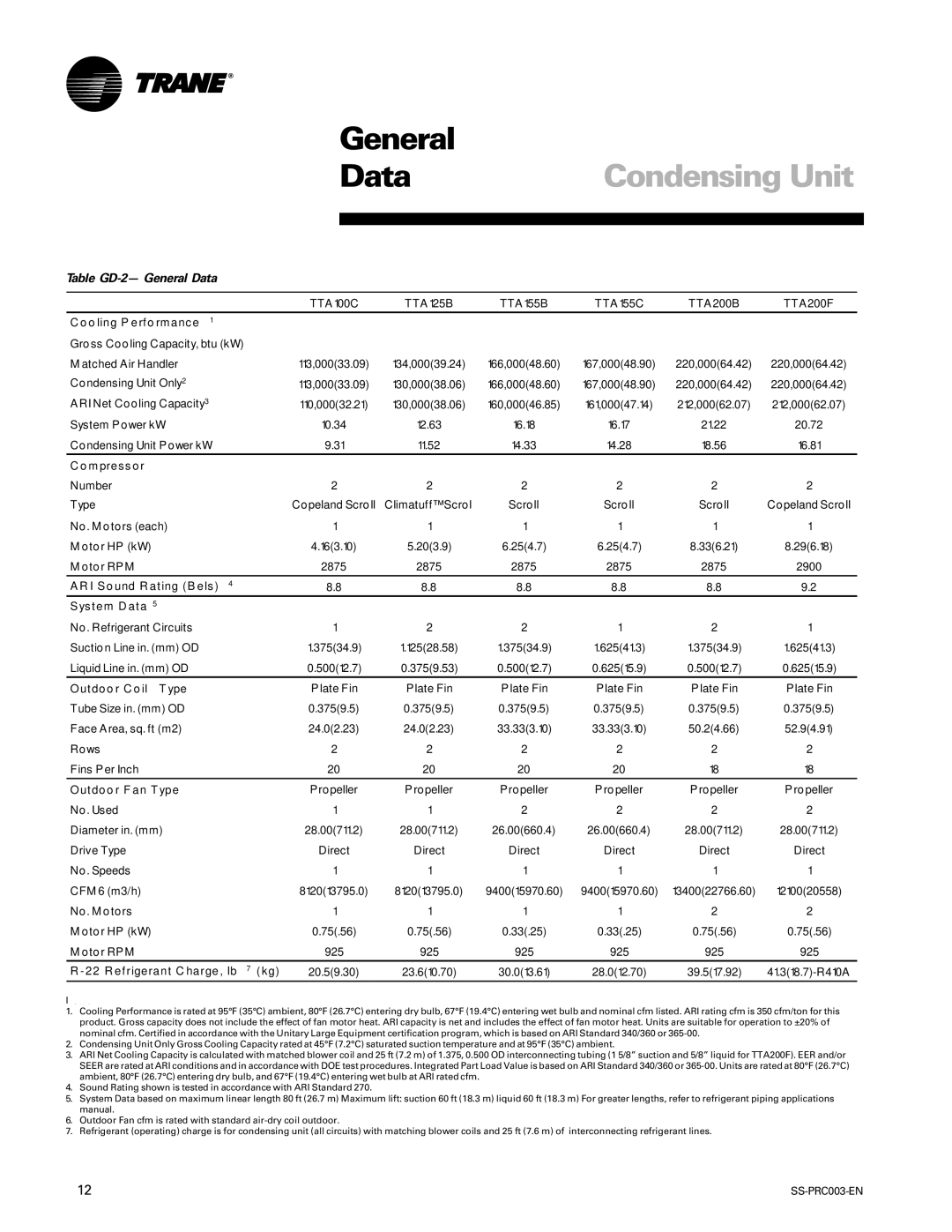
SS-PRC003-EN specifications
The Trane SS-PRC003-EN is a high-efficiency commercial HVAC solution designed to cater to a wide variety of industrial applications. Known for its robust engineering and innovative design, this unit provides reliable climate control, ensuring optimal indoor environments in commercial spaces, manufacturing plants, and large facilities.One of the standout features of the SS-PRC003-EN is its advanced inverter technology. This variable-speed compressor allows for precise cooling and heating adjustments based on real-time demand, which not only enhances system efficiency but also significantly reduces energy consumption. This capability not only minimizes operational costs but also contributes to a more sustainable energy profile, aligning with growing environmental concerns.
Another notable characteristic is its user-friendly control system. The unit is equipped with intuitive interfaces that allow facility managers to monitor and adjust settings remotely. This functionality ensures optimal performance, facilitates maintenance, and offers diagnostics that help identify potential issues before they lead to system failure.
Moreover, the SS-PRC003-EN features a built-in air filtration system that improves indoor air quality. It effectively removes dust, pollutants, and allergens from the air, contributing to healthier environments for occupants. This is particularly critical in commercial settings where many individuals congregate, ensuring compliance with health and safety regulations.
The design also emphasizes noise reduction technology. The unit operates at whisper-quiet levels, minimizing disruption in work environments and enhancing comfort for occupants. This is achieved through a combination of sound-absorbing materials and engineered airflow paths.
Additionally, the Trane SS-PRC003-EN is constructed with durability in mind. It resists corrosion, withstands harsh environmental conditions, and maintains performance longevity, making it a reliable choice for facilities that require constant operation.
With its combination of efficiency, advanced technology, user-friendly controls, and superior air quality management, the Trane SS-PRC003-EN stands out as a market leader in commercial HVAC systems. It offers businesses the performance they need while also promoting energy savings and environmental stewardship, making it an invaluable addition to any commercial infrastructure.

