Trane SSP-PRC001-EN manual Selection Procedure, Cooling Capacity, Heating Capacity

Models: SSP-PRC001-EN

1 64
Download 64 pages 63.31 Kb
Page 8
Image 8

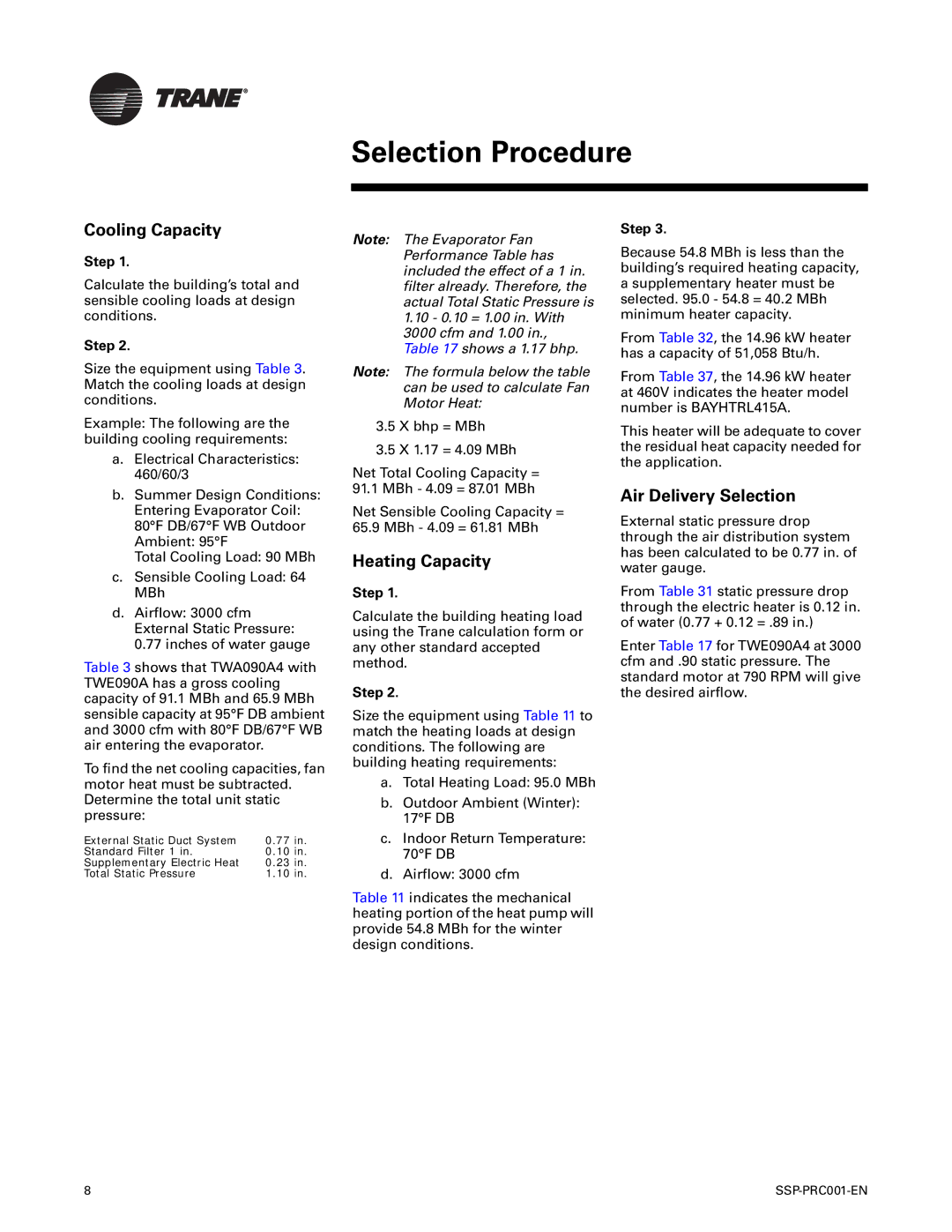
Selection Procedure

Cooling Capacity

Step 1.

Calculate the building’s total and sensible cooling loads at design conditions.

Step 2.

Size the equipment using Table 3. Match the cooling loads at design conditions.

Example: The following are the building cooling requirements:

a.Electrical Characteristics: 460/60/3

b.Summer Design Conditions: Entering Evaporator Coil: 80°F DB/67°F WB Outdoor Ambient: 95°F

Total Cooling Load: 90 MBh

c.Sensible Cooling Load: 64 MBh

d.Airflow: 3000 cfm External Static Pressure: 0.77 inches of water gauge

Table 3 shows that TWA090A4 with TWE090A has a gross cooling capacity of 91.1 MBh and 65.9 MBh sensible capacity at 95°F DB ambient and 3000 cfm with 80°F DB/67°F WB air entering the evaporator.

To find the net cooling capacities, fan motor heat must be subtracted. Determine the total unit static pressure:

External Static Duct System

0.77 in.

Standard Filter 1 in.

0.10 in.

Supplementary Electric Heat

0.23 in.

Total Static Pressure

1.10 in.

Note: The Evaporator Fan Performance Table has included the effect of a 1 in. filter already. Therefore, the actual Total Static Pressure is

1.10- 0.10 = 1.00 in. With 3000 cfm and 1.00 in., Table 17 shows a 1.17 bhp.

Note: The formula below the table can be used to calculate Fan Motor Heat:

3.5 X bhp = MBh

3.5 X 1.17 = 4.09 MBh

Net Total Cooling Capacity = 91.1 MBh - 4.09 = 87.01 MBh

Net Sensible Cooling Capacity = 65.9 MBh - 4.09 = 61.81 MBh

Heating Capacity

Step 1.

Calculate the building heating load using the Trane calculation form or any other standard accepted method.

Step 2.

Size the equipment using Table 11 to match the heating loads at design conditions. The following are building heating requirements:

a.Total Heating Load: 95.0 MBh

b.Outdoor Ambient (Winter): 17°F DB

c.Indoor Return Temperature: 70°F DB

d.Airflow: 3000 cfm

Table 11 indicates the mechanical heating portion of the heat pump will provide 54.8 MBh for the winter design conditions.

Step 3.

Because 54.8 MBh is less than the building’s required heating capacity, a supplementary heater must be selected. 95.0 - 54.8 = 40.2 MBh minimum heater capacity.

From Table 32, the 14.96 kW heater has a capacity of 51,058 Btu/h.

From Table 37, the 14.96 kW heater at 460V indicates the heater model number is BAYHTRL415A.

This heater will be adequate to cover the residual heat capacity needed for the application.

Air Delivery Selection

External static pressure drop through the air distribution system has been calculated to be 0.77 in. of water gauge.

From Table 31 static pressure drop through the electric heater is 0.12 in. of water (0.77 + 0.12 = .89 in.)

Enter Table 17 for TWE090A4 at 3000 cfm and .90 static pressure. The standard motor at 790 RPM will give the desired airflow.

8

SSP-PRC001-EN

Page 8
Image 8
Trane SSP-PRC001-EN manual Selection Procedure, Cooling Capacity, Heating Capacity, Air Delivery Selection

SSP-PRC001-EN specifications

The Trane SSP-PRC001-EN is a state-of-the-art product designed to enhance the efficiency and performance of HVAC systems. As a part of Trane’s expanding suite of smart building technologies, this device integrates advanced features and cutting-edge technology to provide optimal climate control for various applications, including commercial and industrial settings.

One of the primary features of the SSP-PRC001-EN is its ability to monitor and manage energy consumption effectively. The device employs real-time data analytics to provide insights into energy use patterns, allowing facility managers to make informed decisions that can significantly reduce operational costs. By leveraging this information, organizations can optimize their HVAC operations, leading to enhanced sustainability and compliance with environmental regulations.

Another notable characteristic of the SSP-PRC001-EN is its integration with Trane’s smart building technology. The system is designed to seamlessly connect with various sensors and building management systems, creating a comprehensive ecosystem for energy management. Its compatibility with existing infrastructure means that users can upgrade their systems without the need for extensive retrofitting, minimizing disruption while maximizing efficiency.

The SSP-PRC001-EN also boasts user-friendly interfaces that simplify operation and monitoring. Facility managers can easily access data and analytics through intuitive dashboards, which can be customized to display the most relevant information. This ease of use is critical for timely decision-making, especially in environments where rapid response to changing conditions is essential.

In terms of reliability and performance, the SSP-PRC001-EN is built to withstand demanding conditions. Designed with durability in mind, its rugged construction ensures long-lasting service, making it an ideal choice for facilities operating in various environments. Moreover, the system is engineered for flexibility, allowing for adjustments based on specific operational needs.

Overall, the Trane SSP-PRC001-EN combines advanced technology with practical features to deliver an efficient, reliable, and user-friendly solution for HVAC management. Whether for upgrading existing systems or integrating into new buildings, it stands as a testament to Trane's commitment to innovation and sustainability in the realm of climate control solutions. This product exemplifies how technological advancements can contribute to smarter building management and energy efficiency in today's demanding operational landscapes.