Installer’s Guide
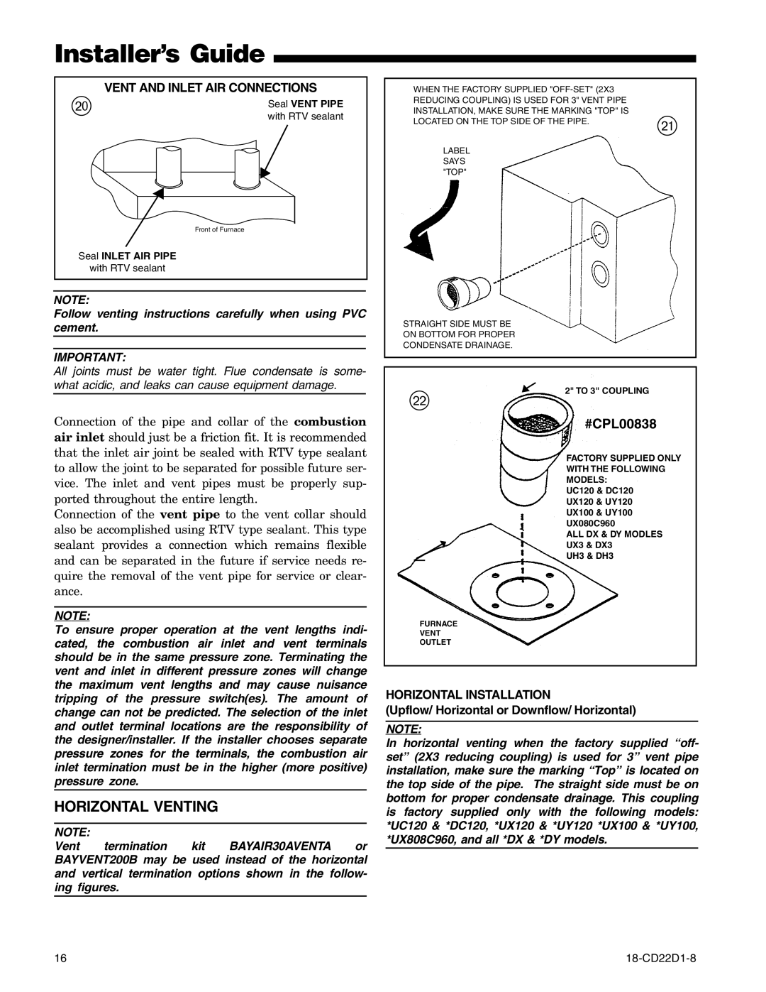
VENT AND INLET AIR CONNECTIONS
p |
|
| Seal VENT PIPE | |
|
|
|
| |
|
|
|
| with RTV sealant |
|
|
|
|
|
|
|
|
|
|
|
|
|
|
|
Front of Furnace
Seal INLET AIR PIPE
with RTV sealant
NOTE:
Follow venting instructions carefully when using PVC cement.
IMPORTANT:
WHEN THE FACTORY SUPPLIED
LOCATED ON THE TOP SIDE OF THE PIPE. | a |
| |
LABEL |
|
SAYS |
|
"TOP" |
|
STRAIGHT SIDE MUST BE
ON BOTTOM FOR PROPER
CONDENSATE DRAINAGE.
All joints must be water tight. Flue condensate is some- what acidic, and leaks can cause equipment damage.
Connection of the pipe and collar of the combustion air inlet should just be a friction fit. It is recommended that the inlet air joint be sealed with RTV type sealant to allow the joint to be separated for possible future ser- vice. The inlet and vent pipes must be properly sup- ported throughout the entire length.
Connection of the vent pipe to the vent collar should also be accomplished using RTV type sealant. This type sealant provides a connection which remains flexible and can be separated in the future if service needs re- quire the removal of the vent pipe for service or clear- ance.
NOTE:
s
2" TO 3" COUPLING
#CPL00838
FACTORY SUPPLIED ONLY WITH THE FOLLOWING MODELS:
UC120 & DC120
UX120 & UY120
UX100 & UY100 UX080C960
ALL DX & DY MODLES UX3 & DX3
UH3 & DH3
To ensure proper operation at the vent lengths indi- cated, the combustion air inlet and vent terminals should be in the same pressure zone. Terminating the vent and inlet in different pressure zones will change the maximum vent lengths and may cause nuisance tripping of the pressure switch(es). The amount of change can not be predicted. The selection of the inlet and outlet terminal locations are the responsibility of the designer/installer. If the installer chooses separate pressure zones for the terminals, the combustion air inlet termination must be in the higher (more positive) pressure zone.
HORIZONTAL VENTING
NOTE:
Vent termination kit BAYAIR30AVENTA or BAYVENT200B may be used instead of the horizontal and vertical termination options shown in the follow- ing figures.
FURNACE
VENT
OUTLET
HORIZONTAL INSTALLATION
(Upflow/ Horizontal or Downflow/ Horizontal)
NOTE:
In horizontal venting when the factory supplied “off- set” (2X3 reducing coupling) is used for 3” vent pipe installation, make sure the marking “Top” is located on the top side of the pipe. The straight side must be on bottom for proper condensate drainage. This coupling is factory supplied only with the following models: *UC120 & *DC120, *UX120 & *UY120 *UX100 & *UY100, *UX808C960, and all *DX & *DY models.
16 |