Installer’s Guide
|
|
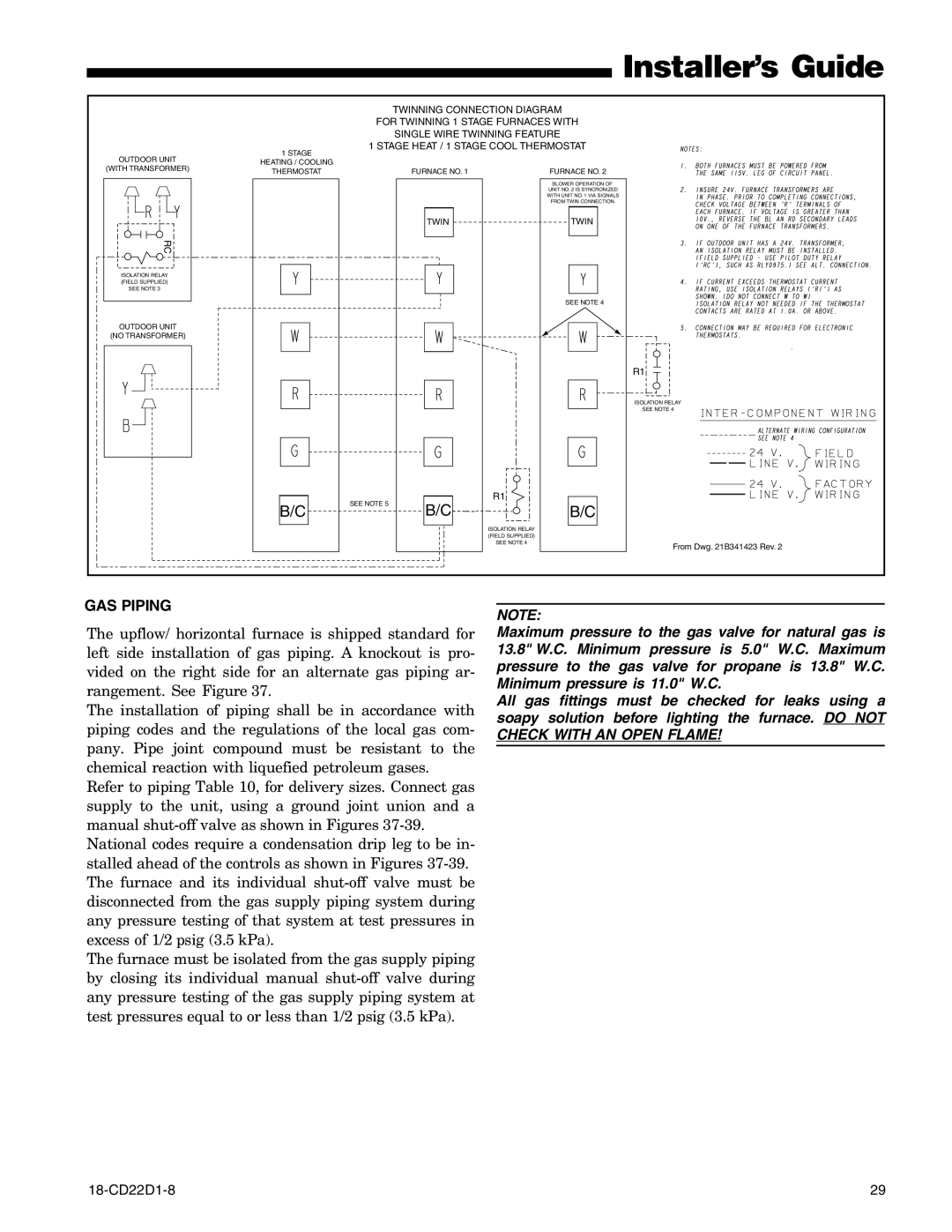
| TWINNING CONNECTION DIAGRAM |
| |
|
| FOR TWINNING 1 STAGE FURNACES WITH |
| ||
|
|
| SINGLE WIRE TWINNING FEATURE |
| |
| 1 STAGE | 1 STAGE HEAT / 1 STAGE COOL THERMOSTAT |
| ||
OUTDOOR UNIT |
|
|
|
| |
HEATING / COOLING |
|
|
|
| |
(WITH TRANSFORMER) |
|
|
|
| |
THERMOSTAT |
| FURNACE NO. 1 | FURNACE NO. 2 |
| |
|
|
| |||
|
|
|
| BLOWER OPERATION OF |
|
|
|
|
| UNIT NO. 2 IS SYNCRONIZED |
|
|
|
|
| WITH UNIT NO. 1 VIA SIGNALS |
|
|
|
|
| FROM TWIN CONNECTION. |
|
|
|
| TWIN | TWIN |
|
RC |
|
|
|
|
|
ISOLATION RELAY |
|
|
|
|
|
(FIELD SUPPLIED) |
|
|
|
|
|
SEE NOTE 3 |
|
|
|
|
|
|
|
|
| SEE NOTE 4 |
|
OUTDOOR UNIT |
|
|
|
|
|
(NO TRANSFORMER) |
|
|
|
|
|
|
|
|
|
| R1 |
|
|
|
|
| ISOLATION RELAY |
|
|
|
|
| SEE NOTE 4 |
|
| SEE NOTE 5 | B/C | R1 |
|
| B/C | B/C |
| ||
|
|
| |||
|
|
|
| ISOLATION RELAY |
|
|
|
|
| (FIELD SUPPLIED) |
|
|
|
|
| SEE NOTE 4 | From Dwg. 21B341423 Rev. 2 |
|
|
|
|
| |
GAS PIPING
The upflow/ horizontal furnace is shipped standard for left side installation of gas piping. A knockout is pro- vided on the right side for an alternate gas piping ar- rangement. See Figure 37.
The installation of piping shall be in accordance with piping codes and the regulations of the local gas com- pany. Pipe joint compound must be resistant to the chemical reaction with liquefied petroleum gases.
Refer to piping Table 10, for delivery sizes. Connect gas supply to the unit, using a ground joint union and a manual
National codes require a condensation drip leg to be in- stalled ahead of the controls as shown in Figures
The furnace must be isolated from the gas supply piping by closing its individual manual
NOTE:
Maximum pressure to the gas valve for natural gas is 13.8" W.C. Minimum pressure is 5.0" W.C. Maximum pressure to the gas valve for propane is 13.8" W.C. Minimum pressure is 11.0" W.C.
All gas fittings must be checked for leaks using a soapy solution before lighting the furnace. DO NOT CHECK WITH AN OPEN FLAME!
29 |