August 7, 2006 | Chapter 2: Installation |
Step | Action |
1Using AWG 16 (1.25mm) solid copper wire, connect one end of the ground wire to the ground stud at the back of the ENIU (shown in Figure
2To assure proper operation, the ground stud must be connected to a good earth ground.
3Connect the other end of the ground wire to the office ground conductor. Ensure this connection is made using methods and hardware that meets all applicable local and national electrical codes.
Figure 2-2. ENIU Rear View with RJ-45 Connector
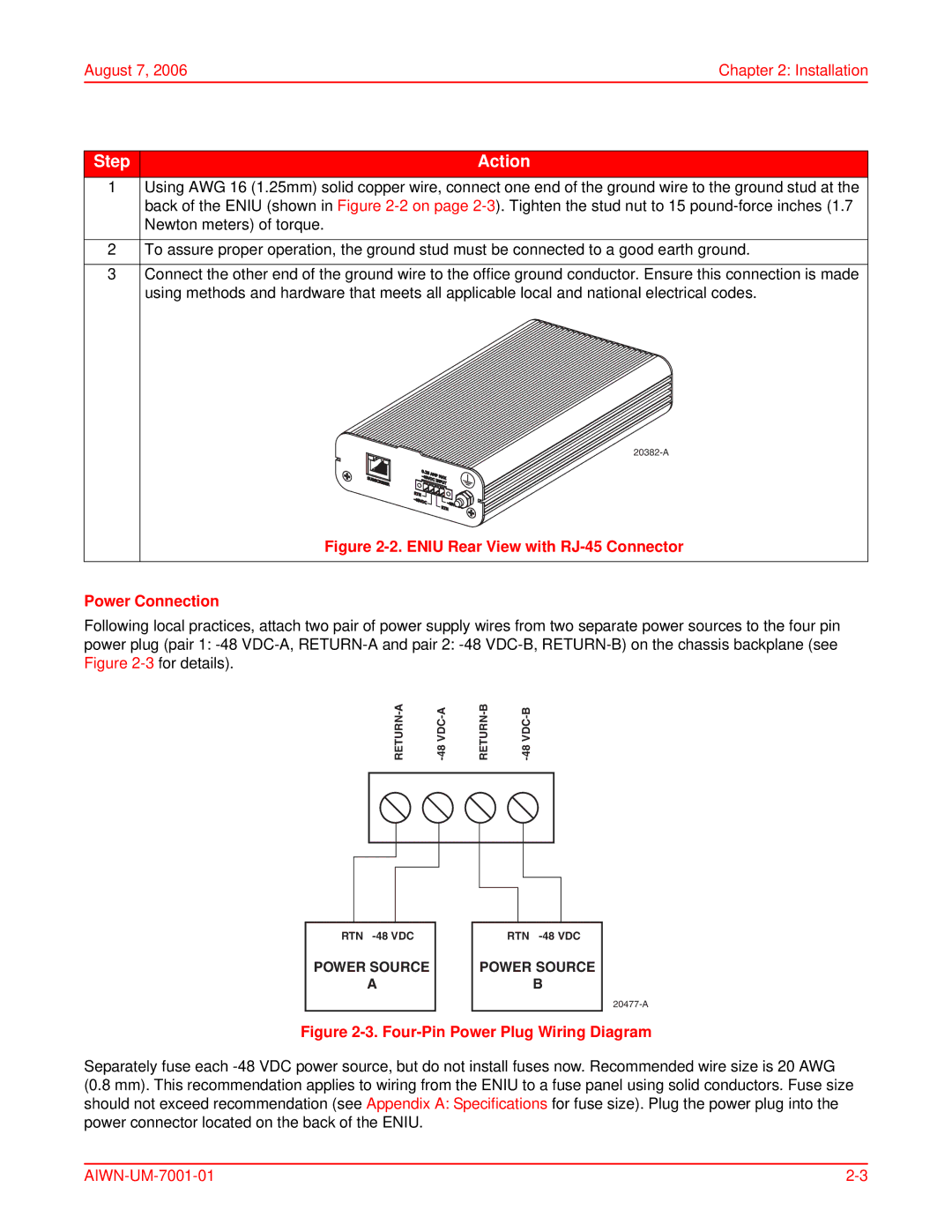
Power Connection
Following local practices, attach two pair of power supply wires from two separate power sources to the four pin power plug (pair 1:
|
| ||||||
|
|
|
|
|
|
|
|
|
|
|
|
|
|
|
|
|
|
|
|
|
|
|
|
|
|
|
|
|
|
|
|
|
|
|
|
|
|
|
|
|
|
|
|
|
|
|
|
|
|
|
|
|
|
|
|
|
|
|
|
|
|
|
|
RTN | RTN |
POWER SOURCE | POWER SOURCE |
A | B |
Figure 2-3. Four-Pin Power Plug Wiring Diagram
Separately fuse each