ADC Network Unit user manual Cabling, Eniu Front View with RJ-45 Connector RJ-45 Ethernet Cables

Models: Network Unit

1 36
Download 36 pages 23.25 Kb
Page 16
Image 16

Chapter 2: Installation

August 7, 2006

CABLING

RJ-45 cable connections are made to both the front and rear of the ENIU. DB-9 (command line interface) connection is made on the front and the power connection is made on the rear. A rear view of the ENIU is shown in Figure 2-2 on page 2-3. A front view is provided below in Figure 2-4.

20383-A1

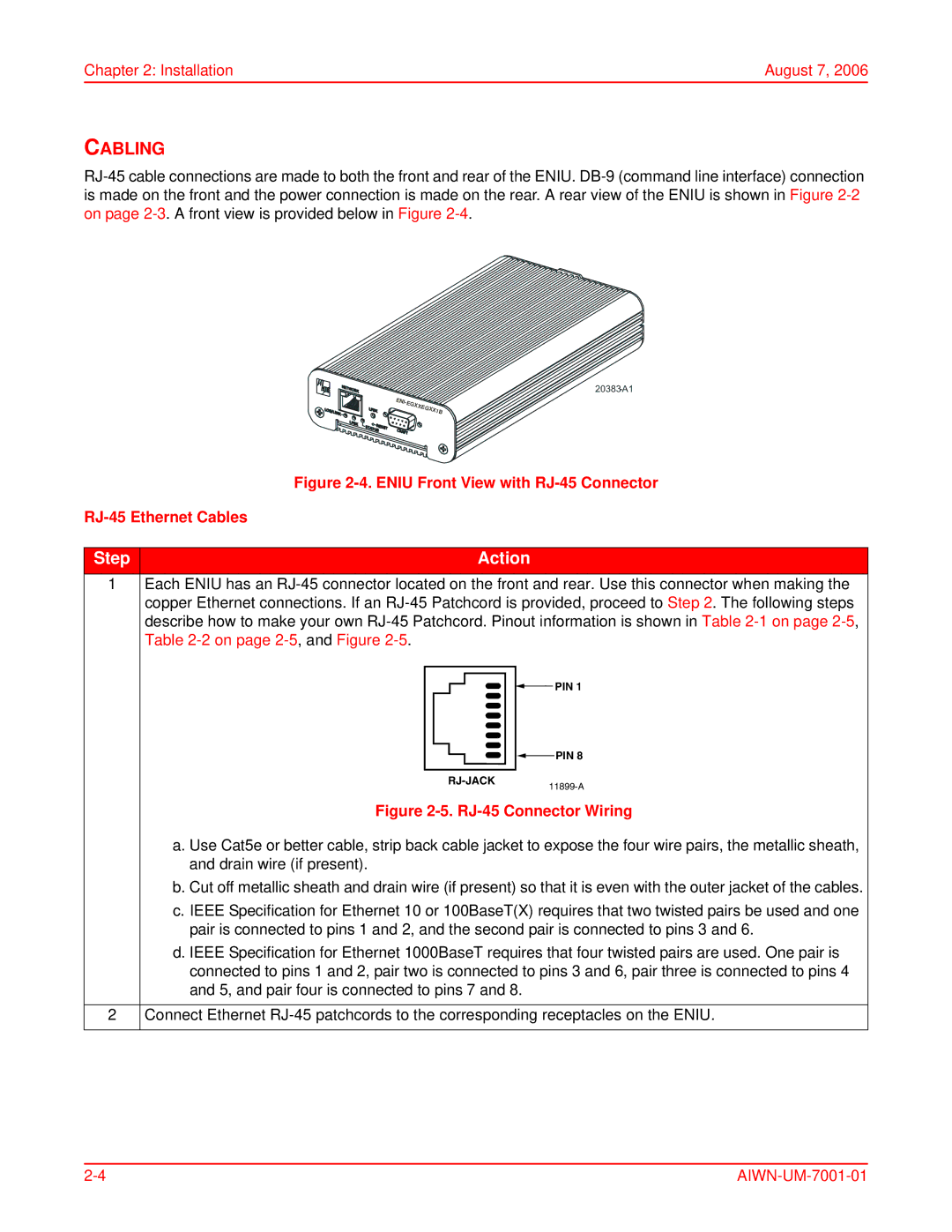
Figure 2-4. ENIU Front View with RJ-45 Connector

RJ-45 Ethernet Cables

Step

Action

1Each ENIU has an RJ-45 connector located on the front and rear. Use this connector when making the copper Ethernet connections. If an RJ-45 Patchcord is provided, proceed to Step 2. The following steps describe how to make your own RJ-45 Patchcord. Pinout information is shown in Table 2-1 on page 2-5, Table 2-2 on page 2-5, and Figure 2-5.

PIN 1


RJ-JACK


PIN 8


11899-A


Figure 2-5. RJ-45 Connector Wiring


a. Use Cat5e or better cable, strip back cable jacket to expose the four wire pairs, the metallic sheath,


and drain wire (if present).


b. Cut off metallic sheath and drain wire (if present) so that it is even with the outer jacket of the cables.


c. IEEE Specification for Ethernet 10 or 100BaseT(X) requires that two twisted pairs be used and one


pair is connected to pins 1 and 2, and the second pair is connected to pins 3 and 6.


d. IEEE Specification for Ethernet 1000BaseT requires that four twisted pairs are used. One pair is


connected to pins 1 and 2, pair two is connected to pins 3 and 6, pair three is connected to pins 4


and 5, and pair four is connected to pins 7 and 8.


2

Connect Ethernet RJ-45 patchcords to the corresponding receptacles on the ENIU.

2-4

AIWN-UM-7001-01

Page 16
Image 16
ADC Network Unit user manual Cabling, Eniu Front View with RJ-45 Connector RJ-45 Ethernet Cables