ALTERNATE UPFLOW FILTER CLIP/
BRACKET INSTALLATION - KIT09224
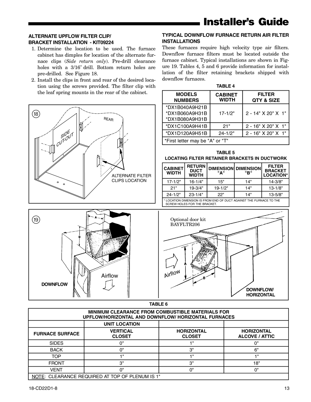
1.Determine the location to be used. The furnace cabinet has dimples for location of the alternate fur- nace clips (Side return only).
2.Install the clips in front and rear of the desired loca- tion using the screws provided. The filter clip with the leaf spring mounts in the rear of the cabinet.
i |
| REAR |
|
| |
| SIDE | |
| - | OUT |
| CUT |
|
ALTERNATE FILTER
CLIPS LOCATION
Installer’s Guide
TYPICAL DOWNFLOW FURNACE RETURN AIR FILTER INSTALLATIONS
These furnaces require high velocity type air filters. Downflow furnace filters must be located outside the furnace cabinet. Typical installations are shown in Fig- ure 19. Tables 4, 5 and 6 provide information for instal- lation of the filter retaining brackets shipped with downflow furnaces.
TABLE 4
MODELS | CABINET | FILTER |
|
NUMBERS | WIDTH | QTY & SIZE |
|
*DX1B040A9H21B |
|
|
|
*DX1B060A9H31B | 2 - 14" X 20" X | 1" | |
*DX1B080A9H31B |
|
|
|
*DX1C100A9H41B | 21" | 2 - 16" X 20" X 1" | |
*DX1D120A9H51B | 2 - 16" X 20" X | 1" | |
*First letter may be "A" or "T"
TABLE 5
LOCATING FILTER RETAINER BRACKETS IN DUCTWORK
CABINET | RETURN | DIMENSION | DIMENSION | FILTER |
DUCT | BRACKET | |||
WIDTH | WIDTH | "A" | "B" | LOCATION* |
|
|
| ||
15" | 14" | |||
21" | 14" | |||
|
| 22" | 14" |
|
* LOCATION DIMENSION IS FROM END OF DUCT AGAINST THE FURNACE TO THE SCREW HOLES FOR THE BRACKET.
o
Airflow
DOWNFLOW
Optional door kit
BAYFLTR206
Airflow
DOWNFLOW/
HORIZONTAL
TABLE 6
MINIMUM CLEARANCE FROM COMBUSTIBLE MATERIALS FOR
UPFLOW/HORIZONTAL AND DOWNFLOW/ HORIZONTAL FURNACES
| UNIT LOCATION |
|
| |
FURNACE SURFACE | VERTICAL | HORIZONTAL | HORIZONTAL | |
CLOSET | CLOSET | ALCOVE / ATTIC | ||
| ||||
SIDES | 0" | 1" | 0" | |
BACK | 0" | 3" | 6" | |
TOP | 1" | 1" | 1" | |
FRONT | 3" | 3" | 18" | |
VENT | 0" | 0" | 0" |
NOTE: CLEARANCE REQUIRED AT TOP OF PLENUM IS 1"
13 |