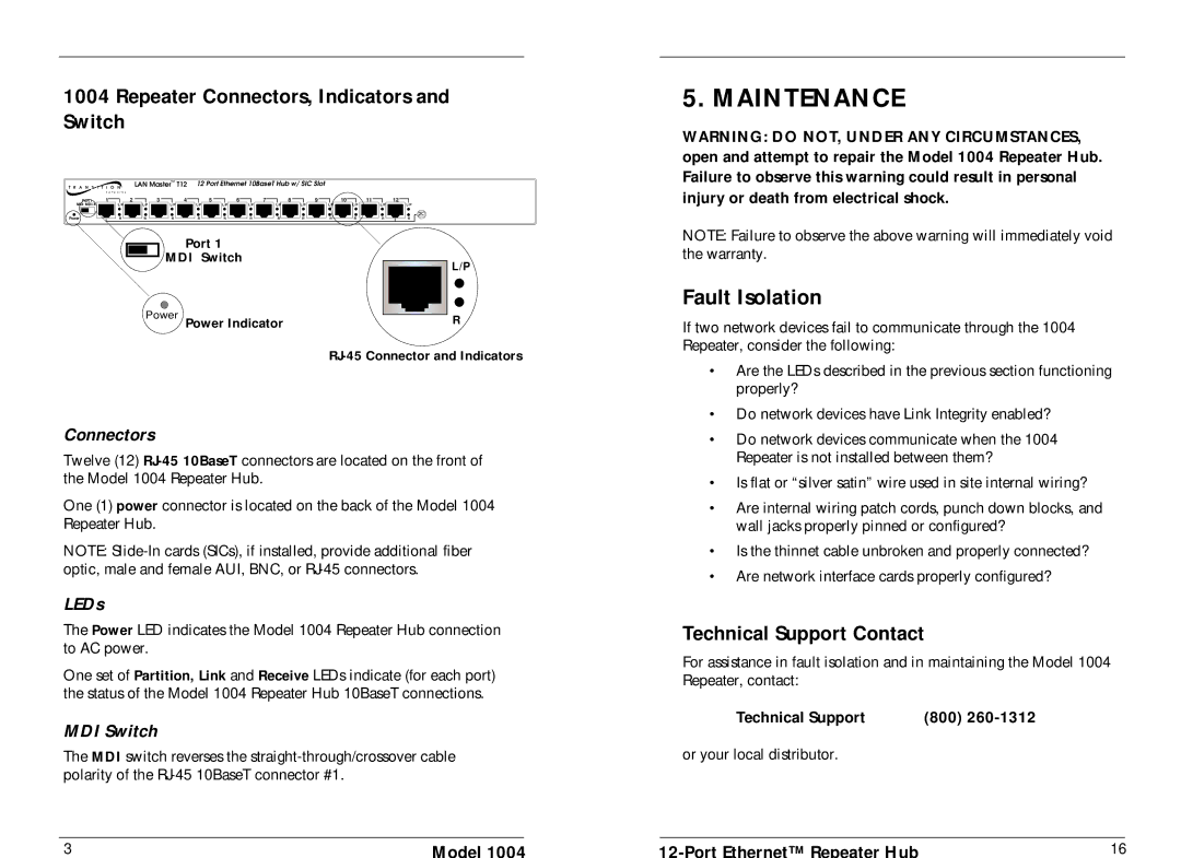
1004 specifications
Transition Networks 1004 is a versatile and robust solution designed to facilitate efficient networking in various environments. It plays a critical role in converting Ethernet signals over long distances and interfacing with a range of network devices. This capability is essential for businesses and organizations looking to maintain high-performance connectivity without compromising on reliability.One of the standout features of the Transition Networks 1004 is its support for Gigabit Ethernet, which allows for high data throughput. This ensures that large files and data-heavy applications can be transmitted quickly and reliably, making it an ideal choice for cloud-based services and data centers. The device also supports various Ethernet standards, making it compatible with a wide range of equipment.
The 1004 is equipped with advanced media conversion technology that enables seamless integration between different media types. It can efficiently convert Ethernet signals from copper to fiber and vice versa. This flexibility allows organizations to extend their network reach without the need for complex or costly infrastructure upgrades. Additionally, the ability to use fiber optics significantly increases transmission distances, reducing latency and improving overall network performance.
Furthermore, this device is designed with high durability in mind. Transition Networks has built the 1004 to withstand harsh environmental conditions, making it suitable for deployment in challenging settings. Its rugged design ensures that it can operate effectively even in areas with extreme temperatures or other environmental stressors.
Ease of installation and operation is another key characteristic of the Transition Networks 1004. The device features user-friendly interfaces and straightforward configuration processes, making it accessible for IT personnel of varying skill levels. This reduces deployment time and minimizes the risk of errors during installation.
In summary, Transition Networks 1004 stands out for its combination of Gigabit Ethernet support, media conversion capabilities, rugged durability, and ease of use. These features make it an optimal choice for organizations seeking reliable and efficient network solutions to meet their growing connectivity demands. Whether in a data center, corporate office, or industrial setting, the Transition Networks 1004 provides the performance and flexibility necessary for modern networking needs.

