Ensuring Correct Segment Number

Ethernet 802.3 specifications define segment number, as well as cable characteristics. (A segment is the cable connection between cable interfaces in an Ethernet LAN.)

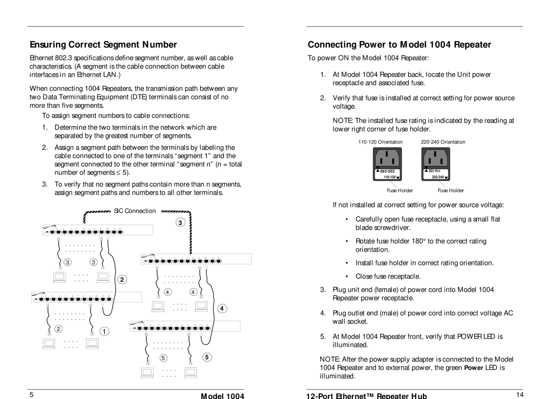
When connecting 1004 Repeaters, the transmission path between any two Data Terminating Equipment (DTE) terminals can consist of no more than five segments.

To assign segment numbers to cable connections:

1.Determine the two terminals in the network which are separated by the greatest number of segments.

2.Assign a segment path between the terminals by labeling the cable connected to one of the terminals “segment 1” and the

segment connected to the other terminal “segment n” (n = total number of segments 5).

3.To verify that no segment paths contain more than n segments, assign segment paths and numbers to all other terminals.

SIC Connection

3

T R A N S I T I O N

1

2

3

4

5

6

7

8

9

10

11

12


. . . . . . . .

. . . . . . . .

T R A N S I T I O N

1

2

3

4

5

6

7

8

9

10

11

12

3 3

Connecting Power to Model 1004 Repeater

To power ON the Model 1004 Repeater:

1.At Model 1004 Repeater back, locate the Unit power receptacle and associated fuse.

2.Verify that fuse is installed at correct setting for power source voltage.

NOTE: The installed fuse rating is indicated by the reading at lower right corner of fuse holder.

110-120 Orientation

220-240 Orientation

240-220

120-110

110-120

220-240

Fuse Holder

Fuse Holder

If not installed at correct setting for power source voltage:

• Carefully open fuse receptacle, using a small flat


blade screwdriver.

Rotate fuse holder 180° to the correct rating


orientation.

Install fuse holder in correct rating orientation.


. . . .


2


. . . .


T R A N S I T

I O N


1

2

3

4

5

6

7

8

9

10


11

12


. . . . . . . .

. . . . . . . .

. . . . . . . .

. . . . . . . .

4 4

. . . .

. . . .

4


• Close fuse receptacle.

3.

Plug unit end (female) of power cord into Model 1004


Repeater power receptacle.

4.

Plug outlet end (male) of power cord into correct voltage AC


wall socket.


T

R

A

N

S

I

T

I

O

N


1


2

3

4

5

6

7

8

9

10

11

12

2

1


. . . .


. . . . . . . .

. . . .


. . . . . . . .


55

. . . .

. . . .

5

Model 1004

5. At Model 1004 Repeater front, verify that POWER LED is

illuminated.

NOTE: After the power supply adapter is connected to the Model 1004 Repeater and to external power, the green Power LED is illuminated.

12-Port Ethernet™ Repeater Hub

14

Page 8
Image 8
Transition Networks specifications Ensuring Correct Segment Number, Connecting Power to Model 1004 Repeater

1004 specifications

Transition Networks 1004 is a versatile and robust solution designed to facilitate efficient networking in various environments. It plays a critical role in converting Ethernet signals over long distances and interfacing with a range of network devices. This capability is essential for businesses and organizations looking to maintain high-performance connectivity without compromising on reliability.

One of the standout features of the Transition Networks 1004 is its support for Gigabit Ethernet, which allows for high data throughput. This ensures that large files and data-heavy applications can be transmitted quickly and reliably, making it an ideal choice for cloud-based services and data centers. The device also supports various Ethernet standards, making it compatible with a wide range of equipment.

The 1004 is equipped with advanced media conversion technology that enables seamless integration between different media types. It can efficiently convert Ethernet signals from copper to fiber and vice versa. This flexibility allows organizations to extend their network reach without the need for complex or costly infrastructure upgrades. Additionally, the ability to use fiber optics significantly increases transmission distances, reducing latency and improving overall network performance.

Furthermore, this device is designed with high durability in mind. Transition Networks has built the 1004 to withstand harsh environmental conditions, making it suitable for deployment in challenging settings. Its rugged design ensures that it can operate effectively even in areas with extreme temperatures or other environmental stressors.

Ease of installation and operation is another key characteristic of the Transition Networks 1004. The device features user-friendly interfaces and straightforward configuration processes, making it accessible for IT personnel of varying skill levels. This reduces deployment time and minimizes the risk of errors during installation.

In summary, Transition Networks 1004 stands out for its combination of Gigabit Ethernet support, media conversion capabilities, rugged durability, and ease of use. These features make it an optimal choice for organizations seeking reliable and efficient network solutions to meet their growing connectivity demands. Whether in a data center, corporate office, or industrial setting, the Transition Networks 1004 provides the performance and flexibility necessary for modern networking needs.