SCSCF30xx-10x
|
|
|
|
|
|
|
|
Part Number |
| Port One - Copper | Port Two - Single Fiber Optic |
|
| ||
|
|
|
|
|
|
|
|
| 75 ohm coax (BNC) |
| SC, 1310 mn (TX)/1550 nm (RX) |
|
| ||
|
|
| |||||
|
|
|
|
| 40 km (24.8 miles)* |
|
|
|
|
|
|
|
|
| |
|
|
|
|
|
|
| |
|
| 75 ohm coax (BNC) | SC, 1550 mn (TX)/1310 nm (RX) |
|
| ||
|
|
|
|
| 40 km (24.8 miles)* |
|
|
|
|
|
|
|
|
|
|
| 75 ohm coax (BNC) | LC, 1300 mn multimode |
|
|
| 2 km (1.2 miles)* |
|
|
|
|
|
*Typical maximum cable distance. Actual distance is dependent upon the physical characteristics of the network: (TX) = transmit, (RX) = receive.
Optional Accessories (sold separately)
Part Number | Description |
|
Optional External Power Supply; |
| |
| Output: 12.6VDC, 1.0 A |
|
|
|
|
Optional External Power Supply; |
| |
| Output: 12.6VDC, 1.0 A |
|
|
|
|
|
Installation -- Continued
CAUTION: Wear a grounding device and observe electrostatic discharge precautions when setting the configuration switches. Failure to observe this caution could result in damage to, and subsequent failure of, the Device.
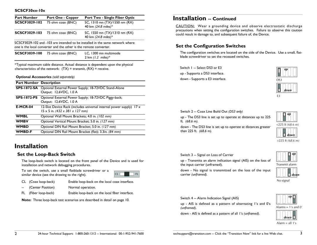
Set the Configuration Switches
The configuration switches are located on the side of the Device. Use a small, flat- blade screwdriver to set the recessed switches.
Switch 1 |
|
|
|
|
|
|
|
| up |
| |
|
|
|
|
| |
up - Supports a DS3 interface. |
|
|
|
|
|
|
|
|
|
| |
down - Supports a E3 interface. |
|
|
|
|
|
DS3 | |||||
down
E3
| 15 x 5 in. (432 x 381 x 127 mm) |
WMBL | Optional Wall Mount Brackets; 4.0 in. (102 mm) |
WMBV | Optional Vertical Mount Bracket; 5.0 in. (127 mm) |
|
|
WMBD | Optional DIN Rail Mount Bracket; 5.0 in. (127 mm) |
Optional DIN Rail Mount Bracket (flat); 3.3in. (84 mm) |
Installation
Set the Loop-Back Switch
The
To set the switch, use a small flatblade screwdriver or a |
|
|
|
|
|
|
|
| ||
|
|
|
|
|
|
|
| |||
similar device (see the drawing to the right). |
| CL |
|
|
|
| FL |
| ||
|
|
|
|
|
| |||||
|
|
|
|
|
|
|
|
|
|
|
|
|
|
|
|
|
|
|
|
|
|
CL | (Coax | Enable |
|
| ||||||
(Center Position) | Normal operation. |
|
|
|
|
|
|
|
| |
FL | (Fiber | Enable |
|
| ||||||
Note: Three
Switch 2
up - The DS3 line is set up to operate at distances up to 225 ft. (68.6 m).
down - The DS3 line is set up to operate at distances greater than 225 ft. (68.6 m).
Switch 3
up - Transmits an alarm indication signal (AIS) on the loss of the input carrier (unframed).
down - No signal is transmitted on the loss of the input carrier (unframed).
Switch 4
up - AIS is defined as a pattern of alternating 1’s and 0’s (unframed).
down - AIS is defined as a pattern of all 1’s (unframed).
![]() up
up
<225 ft (68.6 m)
down
>225 ft (68.6 m)
![]() up
up
Transmit alarm
![]()
![]() down
down
No signal
up ![]()
Alarms = 1's and 0'
down
Alarm = all 1's
2
techsupport@transition.com | 3 |