10KVA specifications
The Tripp Lite 10KVA is a highly versatile and robust uninterruptible power supply (UPS) system designed to provide seamless power protection for critical applications. This unit is ideal for data centers, telecommunications equipment, and industrial applications where power stability is paramount. With a rated capacity of 10,000 VA, it ensures that your equipment remains operational during power outages or fluctuations.One of the key features of the Tripp Lite 10KVA is its advanced battery management system. This technology not only prolongs the life of the batteries but also optimizes their performance. The UPS comes equipped with high-capacity batteries, allowing for extended backup times and ensuring that connected devices can function uninterrupted during emergencies.
Another notable feature is the inverter efficiency, which allows the UPS to convert stored battery power into reliable AC output with minimal loss. This is critical in high-demand scenarios where energy efficiency is essential. The Tripp Lite 10KVA also boasts a wide input voltage range and frequency compatibility, making it suitable for various electrical environments.
The unit incorporates multiple outlets, providing the flexibility to connect diverse devices simultaneously. Additionally, the Tripp Lite 10KVA includes an LCD display, offering real-time data on battery status, load levels, and operating conditions, which aids in proactive management of power resources.
For enhanced safety, the UPS is equipped with numerous protection features, including surge suppression, which protects sensitive equipment from voltage spikes. It also includes built-in circuit breakers to prevent overloads and short circuits, ensuring the safety of both the UPS and connected devices.
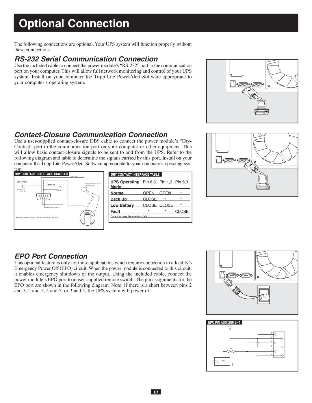
Networking capabilities are another standout characteristic of the Tripp Lite 10KVA. With optional SNMP support, users can monitor the UPS remotely, allowing for effective management and troubleshooting from virtually anywhere. This feature enhances system reliability and contributes to a more efficient operational workflow.
In conclusion, the Tripp Lite 10KVA is a powerful and reliable UPS solution that combines advanced technologies with thoughtful features to deliver unmatched performance. Its robust design, efficiency, and extensive safety measures make it a vital component for any organization looking to safeguard their critical power infrastructure. Whether for business continuity or equipment protection, the Tripp Lite 10KVA stands out as a premier choice in the UPS market.

