3.Installation
3.1UPS Location
Move your UPS over short distances using its wheels. Note: The wheels are not designed to provide
3.2 Mounting Bracket Installation
DANGER!
RISK OF PRODUCT DAMAGE AND SERIOUS PERSONAL INJURY
The UPS System's wheels are not designed to provide
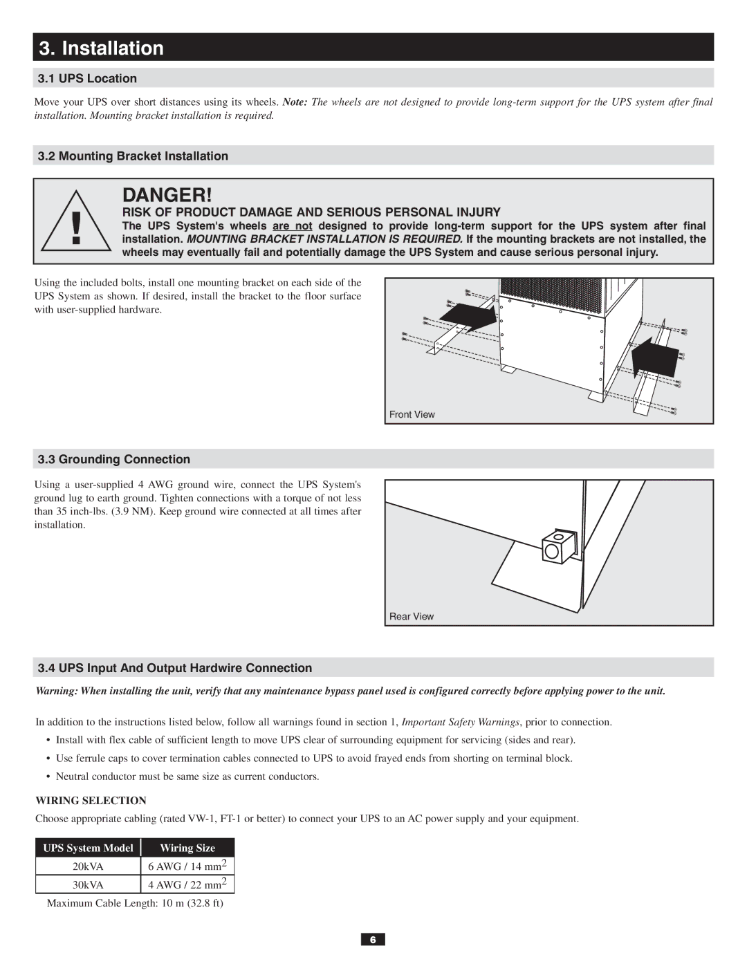
Using the included bolts, install one mounting bracket on each side of the UPS System as shown. If desired, install the bracket to the floor surface with
Front View |
3.3 Grounding Connection
Using a
Rear View |
3.4 UPS Input And Output Hardwire Connection
Warning: When installing the unit, verify that any maintenance bypass panel used is configured correctly before applying power to the unit.
In addition to the instructions listed below, follow all warnings found in section 1, Important Safety Warnings, prior to connection.
•Install with flex cable of sufficient length to move UPS clear of surrounding equipment for servicing (sides and rear).
•Use ferrule caps to cover termination cables connected to UPS to avoid frayed ends from shorting on terminal block.
•Neutral conductor must be same size as current conductors.
WIRING SELECTION
Choose appropriate cabling (rated
UPS System Model
Wiring Size
20kVA | 6 AWG / 14 mm2 |
30kVA | 4 AWG / 22 mm2 |
Maximum Cable Length: 10 m (32.8 ft)
6