Mounting
2-Post (Telecom) Installation
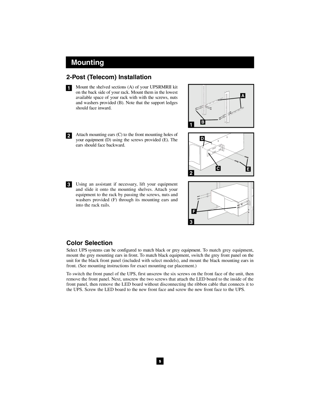
1Mount the shelved sections (A) of your UPSRMRII kit on the back side of your rack. Mount them in the lowest available space of your rack with with the screws, nuts and washers provided (B). Note that the support ledges should face inward.
2Attach mounting ears (C) to the front mounting holes of your equipment (D) using the screws provided (E). The ears should face backward.
3Using an assistant if necessary, lift your equipment and slide it onto the mounting shelves. Attach your equipment to the rack by passing the screws, nuts and washers provided (F) through its mounting ears and into the rack rails.
| A |
1 | B |
| |
| D |
CE
2
F |
3
Color Selection
Select UPS systems can be configured to match black or grey equipment. To match grey equipment, mount the grey mounting ears in front. To match black equipment, switch the grey front panel on the unit for the black front panel (included with select models), and mount the black mounting ears in front. (See mounting instructions for exact mounting ear placement.)
To switch the front panel of the UPS, first unscrew the six screws on the front face of the unit, then remove the front panel. Next, unscrew the two screws that attach the LED board to the inside of the front panel, then remove the LED board without disconnecting the ribbon cable that connects it to the UPS. Screw the LED board to the new front face and screw the new front face to the UPS.
5
