Installation (continued)
Operational Mode Selection
(DIP Switch #4)
The
|
|
| 1 |
| 2 |
| 3 |
| 4 |
|
| ||
|
|
|
|
|
|
|
|
|
|
|
|
| |
Operational Mode | DIP Switch Position |
|
|
|
|
|
|
|
|
|
| ||
|
|
|
|
|
|
|
|
|
| ||||
|
|
|
|
|
|
|
|
|
|
|
| ||
#4 UP |
|
|
|
|
|
|
|
|
|
| |||
|
|
|
|
|
|
|
|
| |||||
|
|
|
|
|
|
|
|
|
|
| |||
|
|
|
| 1 |
| 2 |
| 3 |
| 4 |
|
| |
Economy | #4 DOWN | Economy | |||||||||||
|
|
|
|
|
|
|
|
|
| ||||
|
|
|
|
|
|
|
|
|
| ||||
|
|
|
|
|
|
|
|
|
|
|
| ||
|
|
|
|
|
|
|
|
|
|
|
| ||
|
|
|
|
|
|
|
|
|
|
|
| ||
|
|
|
|
|
|
|
|
|
|
|
| ||
UPS LOCATION
Move your UPS over short distances using its wheels. Stabilize the UPS by releasing the stabilizers on each side of the unit. NOTE: Do not stack the UPS System power module or external battery modules.
INPUT AND OUTPUT CONNECTION
WIRING SELECTION
Choose appropriate cabling (cabling should have a temperature rating of 70° C and 6 AWG size) to connect your UPS to an AC power supply and your equipment to your UPS.
WIRING CONNECTIONS
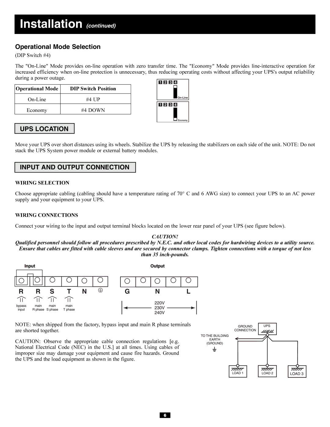
Connect your wiring to the input and output terminal blocks located on the lower rear panel of your UPS (see figure below).
CAUTION!
Qualified personnel should follow all procedures prescribed by N.E.C. and other local codes for hardwiring devices to a utility source. Ensure that cables are fitted with cable sleeves and are secured by connector clamps. Tighten connections with a torque of not less than 35
NOTE: when shipped from the factory, bypass input and main R phase terminals are shorted together.
CAUTION: Observe the appropriate cable connection regulations [e.g. National Electrical Code (NEC) in the U.S.] at all times. Using cables of improper size may damage your equipment and cause fire hazards. Ground the UPS and the load equipment as shown in the figure.
6
