Installation (continued)
WIRING CONNECTION
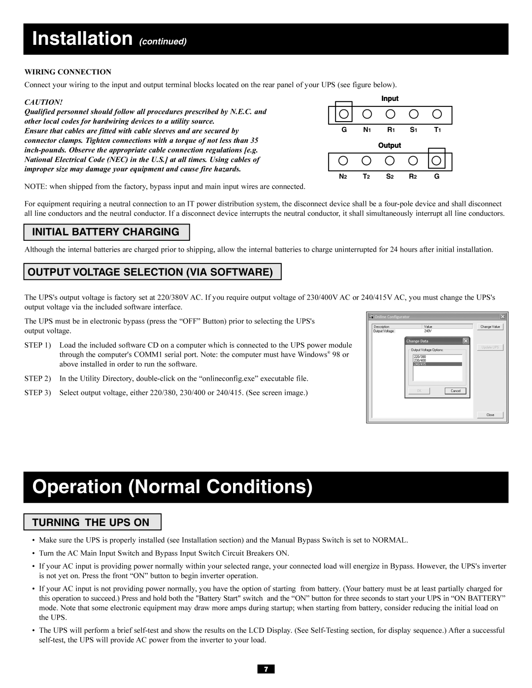
Connect your wiring to the input and output terminal blocks located on the rear panel of your UPS (see figure below).
CAUTION!
Qualified personnel should follow all procedures prescribed by N.E.C. and other local codes for hardwiring devices to a utility source.
Ensure that cables are fitted with cable sleeves and are secured by connector clamps. Tighten connections with a torque of not less than 35
G N1 R1 S1 T1
N2 T2 S2 R2 G
NOTE: when shipped from the factory, bypass input and main input wires are connected.
For equipment requiring a neutral connection to an IT power distribution system, the disconnect device shall be a
INITIAL BATTERY CHARGING
Although the internal batteries are charged prior to shipping, allow the internal batteries to charge uninterrupted for 24 hours after initial installation.
OUTPUT VOLTAGE SELECTION (VIA SOFTWARE)
The UPS's output voltage is factory set at 220/380V AC. If you require output voltage of 230/400V AC or 240/415V AC, you must change the UPS's output voltage via the included software interface.
The UPS must be in electronic bypass (press the “OFF” Button) prior to selecting the UPS's output voltage.
STEP 1) Load the included software CD on a computer which is connected to the UPS power module through the computer's COMM1 serial port. Note: the computer must have Windows® 98 or above installed in order to run the software.
STEP 2) In the Utility Directory,
STEP 3) Select output voltage, either 220/380, 230/400 or 240/415. (See screen image.)
Operation (Normal Conditions)
TURNING THE UPS ON
•Make sure the UPS is properly installed (see Installation section) and the Manual Bypass Switch is set to NORMAL.
•Turn the AC Main Input Switch and Bypass Input Switch Circuit Breakers ON.
•If your AC input is providing power normally within your selected range, your connected load will energize in Bypass. However, the UPS's inverter is not yet on. Press the front “ON” button to begin inverter operation.
•If your AC input is not providing power normally, you have the option of starting from battery. (Your battery must be at least partially charged for this operation to succeed.) Press and hold both the "Battery Start" switch and the “ON” button for three seconds to start your UPS in “ON BATTERY” mode. Note that some electronic equipment may draw more amps during startup; when starting from battery, consider reducing the initial load on the UPS.
•The UPS will perform a brief
7