Battery Connection
Connect your Inverter/Charger to your batteries using the following procedures:
•Connect DC Wiring: Though your Inverter/Charger is a
for brief periods of time. See Specifications page for details. Heavier gauge cabling should be used when continuously operating heavy draw equipment
under these conditions. Tighten your Inverter/Charger and battery terminals to approximately 3.5
•Connect Ground: Using a #8 AWG wire or larger directly connect the Main Ground Lug to earth ground. See the Feature Identification section to locate the Main Ground Lug on your Inverter/Charger. All installations must comply with national and local codes and ordinances.
•Connect Fuse: NEC (National Electrical Code) article 551 requires that you connect all of your Inverter/Charger’s positive DC Terminals directly to a
WARNING!
•Failure to properly ground your Inverter/Charger may result in a lethal electrical shock hazard.
•Never attempt to operate your Inverter/Charger by connecting it directly to output from an alternator rather than a battery or battery bank.
•Observe proper polarity with all DC connections.
Battery Configuration
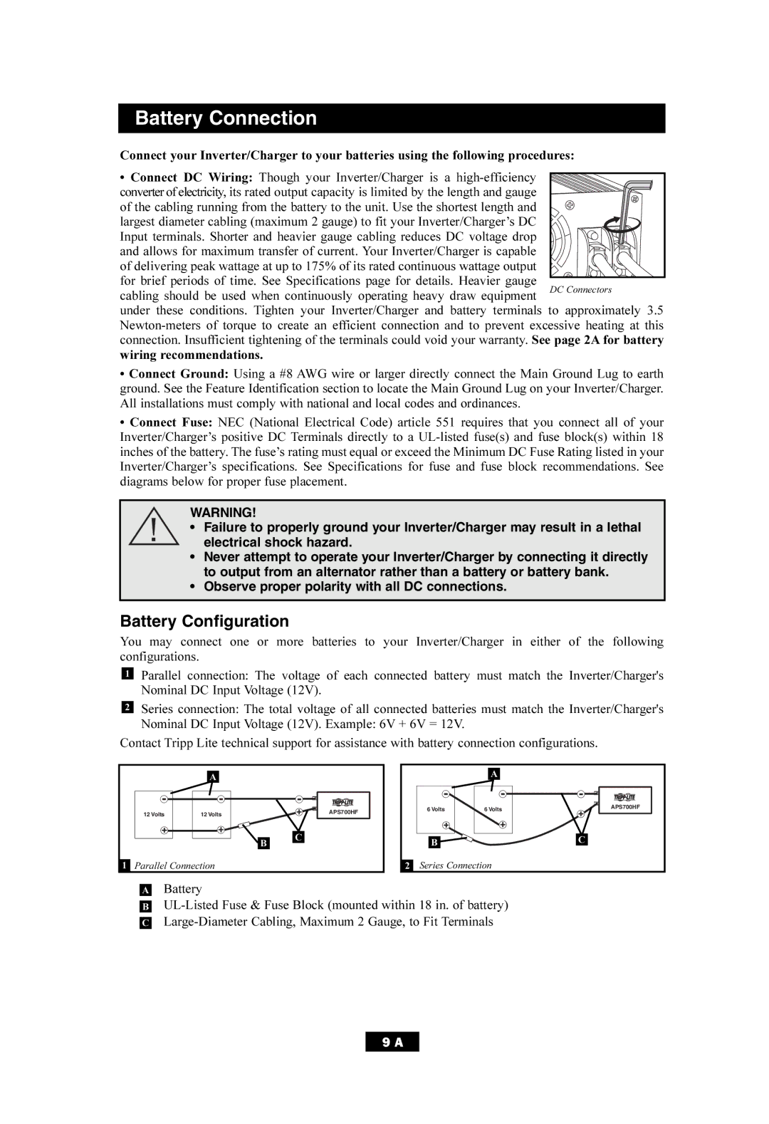
You may connect one or more batteries to your Inverter/Charger in either of the following configurations.
1Parallel connection: The voltage of each connected battery must match the Inverter/Charger's Nominal DC Input Voltage (12V).
2Series connection: The total voltage of all connected batteries must match the Inverter/Charger's
Nominal DC Input Voltage (12V). Example: 6V + 6V = 12V.
Contact Tripp Lite technical support for assistance with battery connection configurations.
| A |
|
12 Volts | 12 Volts | APS700HF |
|
| C |
|
| B |
1Parallel Connection
|
| A |
|
| 6 Volts | 6 Volts | APS700HF |
|
| ||
| B |
| C |
|
|
| |
2 | Series Connection |
| |
ABattery
B
9 A