Rear Panel
REAR PANEL
Individual models may vary slightly from diagram. |
| |
9 |
| |
8 |
| |
6 | 11 | |
5 | ||
10 | ||
7 | ||
12 |
| |
3 | 2 | |
1 |
| |
| 15 | |
| 4 | |
13 |
| |
15 | 14 | |
| ||
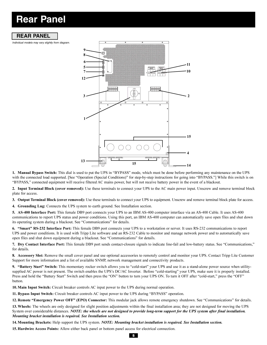
1. Manual Bypass Switch: This dial is used to put the UPS in “BYPASS” mode, which must be done before performing any maintenance on the UPS | ||
with the connected load supported. [See “Operation (Special Conditions)” for | ||
“BYPASS,” connected equipment will receive filtered AC mains power, but will not receive battery power in the event of a blackout. | ||
2. Input Terminal Block (cover removed): Use these terminals to connect your UPS to the AC main power input. Unscrew and remove terminal block | ||
plate for access. |
| |
3. Output Terminal Block (cover removed): Use these terminals to connect your UPS to equipment. Unscrew and remove terminal block plate for access. | ||
4. Grounding Lug: Connects the UPS system to earth ground. See Installation section. |
| |
5. | ||
communications to report UPS status and power conditions. Using this port, an IBM | ||
its operating system during a blackout. See “Communications” for details. |
| |
6. “Smart” | ||
UPS and power conditions. It is used with Tripp Lite software and an | ||
open files and shut down equipment during a blackout. See “Communications” for details. |
| |
7. Dry Contact Interface Port: This female DB9 port sends | ||
for details. |
| |
8. Accessory Slot: Remove the small cover panel and use optional accessories to remotely control and monitor your UPS. Contact Tripp Lite Customer | ||
Support for more information and a list of available SNMP, network management and connectivity products. |
| |
9. “Battery Start” Switch: This momentary rocker switch allows you to | ||
supplied AC power is not present. The switch enables the UPS’s DC/AC Inverter. Before | ||
Press and hold the “Battery Start” Switch and then press the “ON” button to turn your UPS ON. To turn it OFF after | ||
button. |
| |
10. Main Input Switch: Circuit breaker controls AC input power to the UPS during normal operation. |
| |
11. Bypass Input Switch: Circuit breaker controls AC input power to the UPS during “BYPASS” operation. |
| |
12. Remote “Emergency Power OFF” (EPO) Connector: This modular jack allows remote emergency shutdown. See “Communications” for details. | ||
13. Wheels: The wheels are only designed for slight position adjustments within the final installation area; they are not designed for moving the UPS | ||
System over considerable distances. NOTE: the wheels are not designed to provide | ||
Mounting bracket installation is required. See Installation section. |
| |
14. Mounting Brackets: Help support the UPS system. NOTE: Mounting bracket installation is required. See Installation section. | ||
15. Hardwire Access Points: Allow either back panel or bottom panel access for electrical connection. |
| |
5 |
| |
