200308025
Optional Installation
These connections are optional. Your UPS will function properly without these connections.
Basic Operation
Front Panel Switches
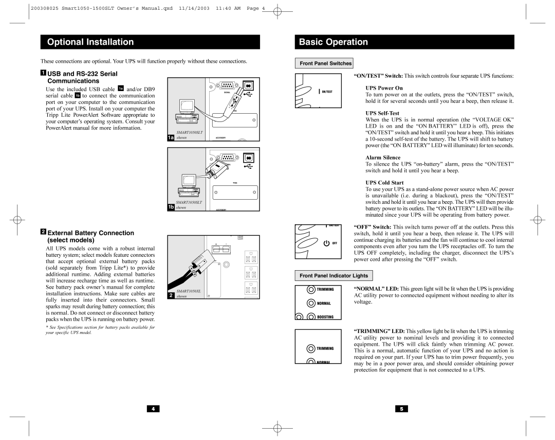
1USB and RS-232 Serial Communications
Use the included USB cable 1a and/or DB9 serial cable 1b to connect the communication port on your computer to the communication port of your UPS. Install on your computer the Tripp Lite PowerAlert Software appropriate to your computer’s operating system. Consult your PowerAlert manual for more information.
2External Battery Connection (select models)
All UPS models come with a robust internal battery system; select models feature connectors that accept optional external battery packs (sold separately from Tripp Lite*) to provide additional runtime. Adding external batteries will increase recharge time as well as runtime. See battery pack owner’s manual for complete installation instructions. Make sure cables are fully inserted into their connectors. Small sparks may result during battery connection; this is normal. Do not connect or disconnect battery packs when the UPS is running on battery power.
*See Specifications section for battery packs available for your specific UPS model.
|
| SIGNAL |
|
| TVSS |
1a | SMART1050SLT |
|
shown | ACCESSORY | |
| ||
|
| TVSS |
| SMART1050SLT |
|
1b shown | ACCESSORY | |
|
| 110V |
|
| 100V |
|
| 127V |
|
| ACCESSORY |
2 | SMART1050XL |
|
shown |
| |
|
|
|
| “ON/TEST” Switch: This switch controls four separate UPS functions: | |
| ON/TEST |
| UPS Power On | ||
|
| To turn power on at the outlets, press the “ON/TEST” switch, | |||
|
|
|
| ||
|
|
|
| hold it for several seconds until you hear a beep, then release it. | |
|
|
|
| UPS | |
|
|
|
| ||
|
|
|
| When the UPS is in normal operation (the “VOLTAGE OK” | |
|
|
|
| LED is on and the “ON BATTERY” LED is off), press the | |
|
|
|
| “ON/TEST” switch and hold it until you hear a beep. This initiates | |
|
|
|
| a | |
|
|
|
| power (the “ON BATTERY” LED will illuminate) for ten seconds. | |
|
|
|
| Alarm Silence | |
|
|
|
| To silence the UPS | |
|
|
|
| switch and hold it until you hear a beep. | |
|
|
|
| UPS Cold Start | |
|
|
|
| To use your UPS as a | |
|
|
|
| is unavailable (i.e. during a blackout), press the “ON/TEST” | |
|
|
|
| switch and hold it until you hear a beep. The UPS will then provide | |
|
|
|
| battery power to its outlets. The “ON BATTERY” LED will be illu- | |
|
|
|
| minated since your UPS will be operating from battery power. | |
| ON/TEST |
|
| “OFF” Switch: This switch turns power off at the outlets. Press this | |
|
| ||||
|
|
|
| ||
|
|
|
| switch, hold it until you hear a beep, then release it. The UPS will | |
| OFF |
|
| continue charging its batteries and the fan will continue to cool internal | |
|
|
| components even after you turn the UPS receptacles off. To turn the | ||
|
|
|
| ||
|
|
|
| UPS OFF completely, including the charger, disconnect the UPS’s | |
|
|
|
| power cord after pressing the “OFF” switch. | |
|
|
|
| ||
|
|
|
|
| |
| Front Panel Indicator Lights |
| |||
|
|
|
|
|
|
TRIMMING | “NORMAL” LED: This green light will be lit when the UPS is providing | |
| AC utility power to connected equipment without needing to alter its | |
NORMAL | voltage. | |
BOOSTING |
| |
| “TRIMMING” LED: This yellow light be lit when the UPS is trimming | |
| ||
| AC utility power to nominal levels and providing it to connected | |
TRIMMING | equipment. The UPS will click faintly when trimming AC power. | |
This is a normal, automatic function of your UPS and no action is | ||
| ||
| required on your part. If your UPS has to trim power frequently, you | |
NORMAL | may be in a poor power area, and should consider obtaining power | |
| ||
| protection for equipment that is not connected to a UPS. |
4 | 5 |